background image


Seite 21 von 170        Artikel Nr.: 1080622001         Stand: 2022_06_24          Technische Änderungen und Irrtümer vorbehalten. 


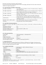
3.3


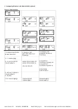
Pictogramme point d´installation (dans la boucle d‘affichage) 

Sur la droite de l'écran dans toutes les boucles d'information, vous trouverez l'un des deux pictogrammes suivants. Le 
pictogramme indique dans quel sens du flux le compteur doit être monté. 


Installation dans le flux retour 


Installation dans le flux aller 


3.4


Pictogrammes de type de compteur (sur l'étiquette d'identification) 


Compteur de chaleur 


Compteur de froid 


4


Installation du calculateur 

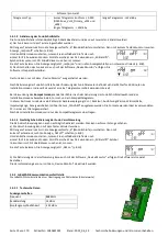
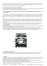
Ouvrez le calculateur en faisant pivoter vers le haut l´étrier sur la partie basse du couvercle. Avant le montage, s’assurer que la 

longueur des câbles soit suffisante. La distance entre les trous de perçage lors du montage avec vis et tampons est de 131 mm, 
voir l’illustration ci-dessous. 
 

Installation sur guide DIN 

Installation directe avec vis et chevilles 


5


Connexion des composants 

Attention 

:

 a

fin d’éviter l’apparition d’un message d’erreur, installez en premier les sondes de température et reliez ensuite le 

mesureur de débit au calculateur

.


Lors de la livraison, le calculateur affiche « H05 » tant que les capteurs de température ne sont pas connectés. 

Dès leur 

connexion et après la première mesure de température, le message d’erreur disparaît sur l‘écran. Sans évolution du volume, 
les mesures de température ont lieu toutes les 15 minutes.


Les connexions du calculateur sont conçues selon les standards en vigueur EN1434-2. Toutes les connections sont marquées 
selon cette norme. 

Le bornier est placé sous le couvercle du calculateur. 
 

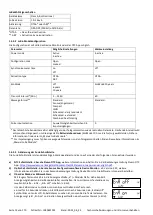
5.1


Connexion des sondes de température  

Veuillez observer les consignes suivantes : 

-


Les capteurs de température doivent avoir les valeurs Pt adaptées au calculateur (Pt 500). Le calculateur reconnaît 
automatiquement les capteurs de température et affiche la valeur Pt dans la boucle d’affichage 2. 

-


Les capteurs de température doivent être montés dans le sens opposé à la direction du flux (jusqu’à DN 100). 

-


Les capteurs de température ne doivent pas être montés dans des zones d’influences thermiques provenant d’autres 
circuits de chauffage. 

-


Il est interdit de plier fortement, allonger ou raccourcir les câbles des sondes. 

-


Si les câbles des sondes de température sont trop longs, ne pas les enrouler autour d’une bobine. Il vaut mieux les 
laisser « libres » ou les enrouler sur eux-mêmes et les lier ensemble à « 8 ». 


Montage 

-


Dévisser les deux presse-étoupes sans bouchons d’obturation et les faire glisser sur les câbles.  

Summary of Contents for Sensus PolluTherm F

Page 1: ...he Vertr glichkeit EMV Richtlinie f r Betriebsmittel 2014 30 EU festgelegt sind Eichrelevante Sicherungszeichen des Rechenwerks d rfen nicht besch digt oder entfernt werden andernfalls entfallen Garan...

Page 2: ...gt das Rechenwerk H 05 im Display an wenn noch keine Temperatursensoren angeschlossen sind Sobald diese angeschlossen wurden und eine erste Messung erfolgte erlischt die Fehlermeldung im Display Ohne...

Page 3: ...er Eingangsimpulswertigkeit des Rechenwerks Beachten Sie hierzu die technischen Daten des Volumenmessteils und vergleichen Sie diese mit den Angaben auf dem Typenschild des Rechenwerks Montage L sen S...

Page 4: ...gsgem er Funktion der Teilger te die Nutzersicherungen an Temperaturf hlern und Volumenmessteil anbringen Das Rechenwerk muss vom Monteur mit der beigegebenen nummerierten Klebeplombe gegen Manipulati...

Page 5: ...ulation gesichert werden Der Barcode Aufkleber kann f r Dokumentationszwecke genutzt werden 7 3 Batterie Austausch Die Batterie des Rechenwerks kann durch autorisierte Personen ausgetauscht werden Es...

Page 6: ...elles Datum im Wechsel mit der Uhrzeit 6 Hinweisanzeige bin re und hexadezimale Anzeige im Wechsel 7 Tarifregister 1 Wert im Wechsel mit Tarifregister und Kriterien 8 Tarifregister 2 Wert im Wechsel m...

Page 7: ...reversion 10 Pt Typ 11 Impulswertigkeit Ebene 3 Statistikschleife 1 30 Halbmonatswerte Datum im Wechsel mit W rmeenergie K lteenergie Volumen Wert Tarifregister 1 Wert Tarifregister 2 1 Bei entspreche...

Page 8: ...ann zum n chsten Men vorschlag gewechselt werden Durch einen langen Tastendruck wird der aktuell angezeigte Men vorschlag bernommen Wird kein Vorschlag best tigt findet keine Umparametrierung statt un...

Page 9: ...in anderen L ndern k nnen ggf hiervon abweichen 10 Hinweiscodes Wenn das Ger t einen Fehler erkannt hat wird im Display das Hinweissymbol angezeigt Der Fehler kann unter dem Men punkt 6 Hinweisanzeig...

Page 10: ...n tig Der Auslesekopf und eine geeignete Konfigurations Software sind optional erh ltlich Die optische Infrarot Schnittstelle wird durch das automatische Senden eines Vorspanns nach EN 13757 3 aktivie...

Page 11: ...stallation muss die Anforderungen der Relevanten Normen Standards Literatur M Bus und folgende Spezifikationen erf llen Maximalspannung M Bus 42 V Minimalspannung M Bus 24 V Maximale berlagerte Spannu...

Page 12: ...ierung der Funk Schnittstelle 1 4 1 wireless M Bus Schnittstelle nach EN 13757 3 4 optional Die Funk Schnittstelle dient zur bertragung von Z hlerdaten Absolutwerte 1 4 1 1 Technische Daten Funk Betri...

Page 13: ...tmodus sendet der Z hler nach der Aktivierung der Funk Schnittstelle w hrend des Installationsmodus abwechselnd ein Format und ein Kompakttelegramm In dieser Zeit muss mindestens ein Z hler der Ger te...

Page 14: ...mationen finden Sie im Manual LoRa Module F r Impulseingang muss Typ Sensus ausgew hlt werden zu den Telegramminhalten finden Sie weitere Informationen im Manual LoRa Module 1 4 2 3 Aktivierung der Fu...

Page 15: ...ft erweist ist die Installationsfirma f r alle resultierenden Kosten verantwortlich 1 5 1 Relevante Normen Standards Literatur Impulseing nge IEC 60364 4 41 2005 12 Low voltage electrical installation...

Page 16: ...st bei Impulsgebern mit Open Collector Ausg ngen zu achten Die Adern d rfen sich w hrend der Installation nicht ber hren da sonst im Ger t Pulse gez hlt werden Beim Einrichten des Z hlers muss gegeben...

Page 17: ...mpulsausg nge OA elektronischer Schalter nach EN 1434 2 2016 L nge Anschlussleitung 1 m Schaltspannung max 30 V Schaltstrom max 27 mA Kontaktwiderstand Ein max 74 Kontaktwiderstand Aus min 6 M Schlie...

Page 18: ...iertem 1 M Widerstand zu verwenden ist dass an einer daf r geeigneten Stelle angeschlossen werden muss Dies ist entweder eine geerdete Rohrleitung oder nur mit entsprechendem Adapter der Schutzkontakt...

Page 19: ...it optional 3 Impulseing ngen 9 M Bus mit optional 3 Impulseing ngen 9 Modbus 10 2 Impulsausg nge oder 2 Anzeige je nach gestecktem Modul und Einstellung wireless M Bus radio off wireless M Bus radio...

Page 20: ...quipements lectriques Le produit satisfait aux exigences essentielles contenues dans la directive europ enne sur la compatibilit lectromagn tique directive CEM 2014 30 EC Les signes relevant de l talo...

Page 21: ...che H05 tant que les capteurs de temp rature ne sont pas connect s D s leur connexion et apr s la premi re mesure de temp rature le message d erreur dispara t sur l cran Sans volution du volume les me...

Page 22: ...impulsion en entr e du calculateur S assurer que les caract ristiques sp cifiques du mesureur de d bit soient conformes celles du calculateur Montage Desserrez le presse toupe central et glissez le s...

Page 23: ...ont elles ouvertes Le circuit thermique est il propre Une diff rence de temp rature plausible est affich e Quand les sous ensembles fonctionnent correctement appliquez les scellements sur les capteurs...

Page 24: ...du module le calculateur doit tre s curis contre la manipulation par un monteur en utilisant l tiquette num rot e destructible par arrachement L autocollant avec code barre peut tre utilis pour votre...

Page 25: ...actuelle 6 Message d information affichage en alternance binaire et hexad cimal 7 Registre tarifaire 1 en alternance avec le n du registre tarifaire et ses crit res 8 Registre tarifaire 2 en alternan...

Page 26: ...1 Valeur d impulsion Niveau 3 Boucle statistique 1 30 Valeurs semi mensuelles Alternant date relev de compteur chaleur froid volume valeur registre tarifaire 1 valeur registre tarifaire 2 1 Suivant l...

Page 27: ...sur le bouton plus longtemps l option affich e sera sauvegard e Si aucune option n est choisie il y aura pas de changement D s que l cran LCD se d sactive le mode d dition se ferme automatiquement b L...

Page 28: ...que le calculateur enregistre un message d information le pictogramme suivant apparait Le message sp cifique peut tre trouv dans l l ment du menu 6 message d information au niveau 1 boucle principale...

Page 29: ...de l environnement longue dur e de fonctionnement H 40 R initialiser Aucune influence sur la mesure Compatibilit lectromagn tique interf rences lectromagn tiques H 20 Electronique d fectueuse Pas de c...

Page 30: ...pas strictement respect es ou si l installation n est pas correcte les frais qui en r sultent seront factur s la soci t responsable de l installation Type de c ble recommand C ble t l phonique J Y ST...

Page 31: ...tomatique 0 d sactiv Valeurs compatibles 1 247 Si l ID esclave automatique est activ r gl sur 1 l adresse M Bus d finie dans le compteur est utilis e pour la communication 1 4 Interfaces radio sans fi...

Page 32: ...La fonction radio peut tre activ e en appuyant sur le bouton poussoir Appuyez sur le bouton longuement jusqu ce que vous passiez la boucle d affichage 6 boucle du module Ensuite appuyez bri vement po...

Page 33: ...ir Appuyez sur le bouton longuement jusqu ce que vous passiez la boucle d affichage 6 boucle du module Ensuite appuyez bri vement sur le 3 me l ment AES off voir image Pour d marrer le mode crypt appu...

Page 34: ...er un symbole stylo d dition appara t dans le coin inf rieur gauche de l cran LCD apr s 2 secondes D s qu il peut tre vu vous devez rel cher le bouton L cran affiche maintenant EnA on et un triangle n...

Page 35: ...oui 1 5 4 Configuration des trois entr es d impulsions suppl mentaires Les entr es d impulsions optionnelles 1 2 3 pour les compteurs externes peuvent tre configur es l aide du logiciel de configurati...

Page 36: ...le 4 fils Couleur Connexion Jaune IA1 Vert IA1 Brun Blanc Sans connexion 1 6 2 Donn es techniques pour une et deux sorties d impulsions Classe de sorties d impulsions OA commutateur lectronique confor...

Page 37: ...installation du module d adaptation respecter les exigences ESD protection lectrostatique conform ment la norme EN 61340 5 1 Cela signifie que sur le lieu de montage du compteur il faut porter un brac...

Page 38: ...tr es d impulsions 9 M bus 3 entr es d impulsions 9 Modbus 10 2 sorties d impulsions oder 2 Affichage en fonction du module branch et de la configuration radio teinte OFF radio branch e ON LoRa on LoR...

Page 39: ...n del consumo de refrigeraci n Se deben observar las normas para instalaciones el ctricas El producto cumple los requisitos esenciales especificados en la Directiva de compatibilidad electromagn tica...

Page 40: ...n tornillos y tacos la distancia entre los orificios debe ser de 131 mm como se muestra en la siguiente figura Montaje con riel en U riel DIN est ndar Montaje con tornillos y tacos 5 Conexi n de los s...

Page 41: ...apretadas Apriete las gl ndulas PG con la mano 5 2 Conexi n de la parte de medici n de volumen El valor de impulso de salida de la parte de medici n de volumen que se debe conectar debe ser id ntico a...

Page 42: ...ecte los fusibles del usuario a los sensores de temperatura y a la parte de medici n de volumen El instalador debe asegurar la unidad aritm tica l gica contra una posible manipulaci n mediante el sell...

Page 43: ...s numerados suministrados junto con los m dulos La etiqueta adhesiva de c digo de barras se puede utilizar con fines de documentaci n 7 3 Cambio de la bater a La bater a de la unidad aritm tica l gica...

Page 44: ...lso 2 4 Volumen acumulado en m 5 Fecha actual en alternancia con la hora 6 Mensajes visualizaci n binaria y hexadecimal en alternancia 7 Registro de tarifas 1 Valor en alternancia con registro de tari...

Page 45: ...Direcci n de M Bus 8 N mero de serie 9 Versi n del firmware 10 Tipo de Pt 11 Valor de impulso Nivel 3 bucle estad stico 1 30 Valores de medio mes fecha en alternancia con energ a de calefacci n energ...

Page 46: ...s de 2 segundos aparece el l piz de edici n en la parte inferior izquierda de la pantalla LCD v ase la figura Debe dejar de pulsar la tecla tan pronto como aparezca La indicaci n actual comenzar enton...

Page 47: ...s sensores de temperatura Resistencia de precisi n de platino Pt 500 Longitud del cable de conexi n sin blindaje m Hasta 10 en configuraci n de 2 hilos Tipo de instalaci n inmersi n directa en manguit...

Page 48: ...n 1 2 3 4 5 6 7 8 Visualizaci n de mensaje alternante binaria LCD En el caso de que se muestre cualquiera de los mensajes que aparecen en la pantalla est ndar cantidad acumulada de calor con la excep...

Page 49: ...e Cable telef nico J Y ST Y 2x2x0 8mm Es importante asegurarse de que la topolog a de la red M Bus longitudes de cables y secciones transversales es adecuada para la velocidad en baudios 2400 Bd de lo...

Page 50: ...az de comunicaci n LoRaWAN consulte el cap tulo 1 4 2 Informaci n general sobre la interfaz radio Debe evitarse la instalaci n de componentes de radio entre o detr s de las tuber as de calefacci n o e...

Page 51: ...eja la f brica desactivada Se puede activar de la siguiente manera a La funci n radio se puede activar pulsando el pulsador Presione el pulsador hasta que cambie al lazo de visualizaci n 6 lazo del m...

Page 52: ...r 1 4 2 Interfaz de comunicaci n LoRaWAN La interfaz LoRaWAN se utiliza para transferir datos del medidor valores absolutos 1 4 2 1 Especificaciones t cnicas Propiedades de radio Frecuencia 868 MHz Po...

Page 53: ...didor est buscando la red LoRaWAN aparecer LorA Pen en la pantalla LCD el tiempo entre cada intento de conexi n se reduce gradualmente a al menos una vez al d a Tan pronto el contador se haya conectad...

Page 54: ...s de impulsos no se vean afectados por una tensi n externa Compruebe la polaridad de los generadores de impulsos con salidas de colector abierto Los hilos de los cables no deben tocarse durante la ins...

Page 55: ...h pulso 10 Mcal pulso 10 MJ pulso 10 MMBTU pulso POLLUSTAT salida de impulsos para volumen Para el valor de impulso siempre se aplica Visualizaci n en m Valor de impulso 100 l pulso 0 1 m pulso POLLUT...

Page 56: ...r n IA2 Blanco IA2 2 Reequipamiento de una interfaz de comunicaci n adicional Al instalar el m dulo de ampliaci n se deben tener en cuenta los requisitos ESD seg n EN 61340 5 1 En el lugar de instalac...

Page 57: ...a de impulsos 8 M Bus inal mbrico 3 entradas de impulsos 9 M Bus 3 entradas de impulsos Modbus 10 2 salidas de impulsos o 2 Pantalla dependiendo del m dulo enchufado y la configuraci n Radio off Radio...

Page 58: ...ondizioni del rapporto CEN TR 16911 e della VDI 2035 Osservare le normative nazionali relative alla misurazione delle frigorie Osservare le prescrizioni relative all installazione delle apparecchiatur...

Page 59: ...li 5 Collegamento dei componenti Avvertenza installare prima le sonde di temperatura poi collegare il contatore d acqua all unit elettronica In questo modo non verranno generati messaggi di errore Fin...

Page 60: ...contatore d acqua e l ingresso impulsi dell unit elettronica devono avere lo stesso valore impulsi Verificare che le caratteristiche del contatore d acqua siano compatibili con le caratteristiche dell...

Page 61: ...i filtri sono ostruiti La differenza di temperatura visualizzata verosimile Dopo aver verificato il corretto funzionamento dei componenti applicare i sigilli antimanomissione alle sonde di temperatur...

Page 62: ...r installato l interfaccia l installatore deve applicare all unit elettronica il sigillo adesivo antimanomissione Il sigillo numerato Ogni sigillo numerato viene fornito assieme a un adesivo con un co...

Page 63: ...e totale in m 5 Data corrente alternata all ora 6 Messaggio di errore formato binario ed esadecimale alternati 7 Registro tariffario 1 valore alternato al registro tariffario e ai parametri 8 Registro...

Page 64: ...M Bus 8 Numero di matricola 9 Versione firmware 10 Designazione Pt 11 Valore impulso Men 3 Men dei dati statistici 1 30 Valori quindicinali data alternata a calorie frigorie volume valore del registro...

Page 65: ...e Se l opzione non viene confermata il parametro non verr impostato e lo strumento uscir dalla modalit di modifica b I seguenti parametri sono disponibili per l unit elettronica nella versione compati...

Page 66: ...se alle disposizioni nazionali 10 Messaggi di errore Quando lo strumento rileva un errore il display visualizza questo simbolo L errore viene visualizzato nel men 1 alla voce 6 Messaggio di errore v 8...

Page 67: ...ra permette di effettuare 4 comunicazioni Se le letture sono meno frequenti il numero di comunicazioni disponibili aumenta 1 2 Interfaccia M Bus su richiesta L M Bus un interfaccia per la trasmissione...

Page 68: ...bus Consumo Massimo 500 mW Protocollo di comunicazione Modbus RTU Canale EIA 485 isolato galvanicamente Baud rate 1200 2400 4800 9600 14400 19200 38400 56000 57600 115200 1 3 2 Configurazione di fabbr...

Page 69: ...mpostazioni disponibili Impostazioni di fabbrica Vita utile stimata della batteria 10 anni Modo di trasmissione S1 T1 C1 unidirezionale T1 unidirezionale Periodo di trasmissione 00 00 24 00 8 00 18 00...

Page 70: ...o a quando viene visualizzato il men 6 Premere brevemente il pulsante ancora una volta per visualizzare la seconda voce AES off v figura Per attivare la modalit di modifica premere nuovamente il pulsa...

Page 71: ...are il circuito 6 circuito del modulo cfr capitolo 3 Visualizzazione del circuito del modulo opzionale quindi passare al secondo circuito con una breve pressione del pulsante 6 02 EnA oFF cfr immagine...

Page 72: ...lasse degli ingressi impulsi IB in conformit alla Norma EN 1434 2 2016 Lunghezza del cavo di collegamento 1 m Tensione di alimentazione 3 V cc Corrente di sorgente 1 5 A Livello alto di tensione di in...

Page 73: ...mpulso uscita impulsi 1 nel men 6 men delle interfacce Il firmware in versione 1 03 e nelle versioni successive PolluStat in versione 1 00 e nelle versioni successive PolluStat PolluTherm F riconosce...

Page 74: ...ay 0 000 m valore impulso 10 l impulso 0 01 m impulso 1 7 1 Collegamento a 4 fili Colore Collegamento Giallo IA1 Verde IA1 Marrone IA2 Bianco IA2 2 Installazione successiva di un interfaccia di comuni...

Page 75: ...bbinato a un adesivo con un codice a barre che pu essere utilizzato a scopo di riferimento 3 Men delle interfacce moduli su richiesta Men 6 Men delle interfacce moduli 1 Visualizzazione alternata dell...

Page 76: ...lations must be observed This product fulfils the requirements of the European Council Directive on Electromagnetic Compatibility EMC Directive 2014 30 EU The identification plate of the instrument an...

Page 77: ...he center to center drill hole separation for the direct screw mounting is in the following picture 131 mm With commonly available mounting rail Direct screw mounting 5 Connecting the Components Impor...

Page 78: ...ensor must always be connected to clamp 7 and 8 outlet The color of the wires does not matter Check that the connections are tight Screw the cable glands tight by hand 5 2 Mounting the flow meter The...

Page 79: ...cooling system clear dirt filters not clogged Is a plausible temperature difference displayed When the components are functioning properly attach the seals to the temperature sensors and the flow mete...

Page 80: ...The added bar code label can be used for the purpose of documentation 7 3 Exchanging the battery The calculator s battery is easy to exchange by authorized technical personnel our replacements only Re...

Page 81: ...f register no and criteria 8 Tariff register 2 value alternating with tariff register no and criteria 9 Pulse counter 1 pulse value alternating with reading2 10 Pulse counter 2 pulse value alternating...

Page 82: ...Maximum power alternating with date and time 2 Maximum flow alternating with date and time 3 Maximum inlet flow temperature alternating with date and time 4 Maximum outlet flow temperature alternating...

Page 83: ...tection of flow As long as the calculator detects some flow the following pictogram will be displayed bottom right in the LCD flow detected 8 3 Volume pulses When a volume pulse is received via the ca...

Page 84: ...e sensor outlet flow cable break 1 at sixth place H 02 Temperature sensor inlet flow short circuit 1 at seventh place H 01 Temperature sensor inlet flow cable break 1 at eighth place Example Temperatu...

Page 85: ...ating instruction manuals are not strictly followed or if the installation is shown to be faulty any resulting expenses will be charged to the company responsible for the installation Recommended type...

Page 86: ...automatic Slave ID is activated set to 1 the M Bus address which is set in the meter is used for communication 1 4 Wireless Interfaces Sensus offers the following radio interfaces wireless M Bus inter...

Page 87: ...conds 240 minutes 120 seconds heat meters Weekdays Monday Sunday any weekday Monday Friday Weeks in a month 1 4 4 uninterrupted incl a possible 5th week 1 4 4 uninterrupted Months 1 12 1 12 Radio acti...

Page 88: ...op Then change with a brief keystroke to the 3rd item AES off see picture In order to start the editing mode you afterwards must press the push button once again for 2 3 seconds As an aid after 2 seco...

Page 89: ...n aid an editing pen symbol appears in the lower left corner of the LCD after 2 seconds As soon as it can be seen you must release the button The display now shows EnA on and a black triangle in all d...

Page 90: ...o yes no no Class OE no no no no yes 1 5 4 Setting up the three additional pulse inputs The optional pulse inputs 1 2 3 for external meters can be set up using a suitable configuration software You ca...

Page 91: ...shows kWh MWh Display shows Gcal Display shows GJ Display shows MMBTU qp 0 6 m3 h 1 kWh pulse 1 Mcal pulse 10 MJ pulse 10 MMBTU pulse qp 1 5 m3 h 1 kWh pulse 1 Mcal pulse 10 MJ pulse 10 MMBTU pulse q...

Page 92: ...volume The pulse value for volume is always determined by the second to last place of the volume display Example Display 0 000 m pulse value 10 l pulse 0 01 m pulse 1 7 1 Pin assignments 4 wire cable...

Page 93: ...ainst unauthorized opening using one of the numbered adhesive seals enclosed to the modules stick it upon the seal destroyed The added bar code label can be used for the purpose of documentation 3 Dis...

Page 94: ...ektromagnetycznej dyrektywa EMC dla urz dze 2014 30 EU Nie wolno uszkadza ani usuwa znacznik w bezpiecznik w kalibracyjnych przelicznika w przeciwnym razie traci si gwarancj i okres kalibracji urz dze...

Page 95: ...alkulator pokazuje na wy wietlaczu H 05 je eli nie ma jeszcze pod czonych czujnik w temperatury Gdy tylko zostan one pod czone i zostanie wykonany pierwszy pomiar komunikat o b dzie zniknie z wy wietl...

Page 96: ...czna z cz stotliwo ci impuls w wej ciowych kalkulatora Zwr ci uwag na dane techniczne cz ci do pomiaru obj to ci i por wna je z danymi na tabliczce znamionowej kalkulatora Monta Poluzowa rodkowe po cz...

Page 97: ...ostki dzia aj prawid owo nale y pod czy bezpieczniki u ytkownika do czujnik w temperatury i sekcji pomiaru obj to ci Kalkulator musi by zabezpieczony przed manipulacj przez instalatora za pomoc numero...

Page 98: ...ch 7 3 Wymiana baterii Baterie kalkulatora mog by wymieniane przez osoby upowa nione Mo na u ywa tylko naszych oryginalnych baterii Wymienione baterie nale y utylizowa w spos b przyjazny dla rodowiska...

Page 99: ...ch 2 5 Aktualna data na zmian z godzin 6 Wy wietlacz informacyjny wy wietlanie binarne i szesnastkowe na przemian 7 Rejestr taryfowy 1 warto na zmian z rejestrem taryfowym i kryteriami 8 Rejestr taryf...

Page 100: ...kWh 7 Adres M Bus 8 Numer serii 9 Wersja oprogramowania sprz towego 10 Typ Pt 11 Warto ci impulsu Poziom 3 P tla statystyczna 1 30 Warto ci p miesi czne Data na zmian z energi ciep a energi zimna obj...

Page 101: ...nie zacznie miga aktualne wy wietlanie Do nast pnej propozycji menu mo na przej naciskaj c kr tko przycisk Nacisn i przytrzyma przycisk aby zaakceptowa aktualnie wy wietlan propozycj menu Je li adna s...

Page 102: ...zimna Obszar zastosowa pomiary ciep a zimna Oznaczenie UE i oddzielne krajowe zatwierdzenie typu jako czujniki temperatury do licznik w zimna Wymagania w innych krajach mog si r ni 10 Kody informacyj...

Page 103: ...troli 10 1 Opis informacji Wy wietlacz Wskaz wka Dzia anie Mo liwa przyczyna H 80 S aba bateria Brak wp ywu na obliczenia Niekorzystne warunki rodowiskowe d ugi okres u ytkowania H 40 Reset Brak wp yw...

Page 104: ...w przypadku wadliwej instalacji firma instalacyjna jest odpowiedzialna za wszystkie wynikaj ce z tego koszty Zalecany typ przewodu Kabel telefoniczny J Y ST Y 2x2x0 8mm Nale y zwr ci uwag na to aby t...

Page 105: ...est wykorzystywany adres M Bus ustawiony wcze niej w liczniku 1 4 Interfejsy bezprzewodowe Sensus oferuje nast puj ce interfejsy radiowe bezprzewodowy interfejs M Bus zgodny z norm EN 13757 3 4 patrz...

Page 106: ...01 i _v402 d ugi telegram Walk by d ugi telegram Walk by 1 4 1 3 Aktywacja interfejsu radiowego Interfejs radiowy jest domy lnie wy czony i mo e by aktywowany na dwa sposoby a Radio mo na w czy za pom...

Page 107: ...ia mo na r wnie wykona za pomoc oprogramowania Device Monitor Software zamawia si oddzielnie Kodowanie mo na dezaktywowa tylko za pomoc Device Monitor 1 4 2 Interfejs komunikacyjny LoRaWAN Interfejs L...

Page 108: ...homi tryb edycji nale y jeszcze raz nacisn przycisk nacisn raz na 2 3 sekundy Jako pomoc po 2 sekundach w lewej dolnej cz ci wy wietlacza LCD pojawia si symbol pi ra edycyjnego Gdy tylko b dzie to wid...

Page 109: ...rno ko cowa 2 M D ugo impulsu 100 ms Cz stotliwo ko cowa 5 Hz 1 5 3 Powszechne zastosowanie urz dze wej ciowych klasa IB i wyj ciowych klasa OA Klasa IA Klasa IB Klasa IC Klasa ID Klasa IE Klasa OA Ta...

Page 110: ...impulsowe 1 w p tli wska nikowej 6 p tla modu owa Po pod czeniu modu u licznik rozpoznaje wielko nominaln oraz wskazanie energii i ustawia warto ci impuls w dla energii i obj to ci niezale nie zgodnie...

Page 111: ...nie przy czy kabel 4 y owy Kolor Przy cze ty IA1 zielony IA1 br zowy IA2 bia y IA2 3 Doposa enie w dodatkowy interfejs komunikacyjny Podczas instalacji modu u rozszerze nale y przestrzega wymaga ESD z...

Page 112: ...ulsowymi 9 M Bus z opcjonalnymi 3 wej ciami impulsowymi 9 Modbus 10 2 Wyj cia impulsowe lub 2 Wy wietlanie w zale no ci od pod czonego modu u i ustawienia wireless M Bus radio off wireless M Bus radio...

Page 113: ...d Irrt mer vorbehalten PolluTherm F DE 18 MI004 PTB037 MID DE 18 M PTB 0049 CH T2 18769 00 1 PolluTherm F 2 PolluStat PolluTherm F 3 3 1 EN 1434 1 6 2014 32 I MI 004 EN 1434 6 PTB TR K 8 TR K 9 2014 3...

Page 114: ...Seite 114 von 170 Artikel Nr 1080622001 Stand 2022_06_24 Technische nderungen und Irrt mer vorbehalten 3 3 3 4 4 131 DIN 5 H 05 15 EN 1434 2 5 1 Pt Pt 500 Pt 2 DN 100...

Page 115: ...Seite 115 von 170 Artikel Nr 1080622001 Stand 2022_06_24 Technische nderungen und Irrt mer vorbehalten PG PG 5 6 7 8 PG 5 2 PG PG 10 11 Open Collector PG PG PG...

Page 116: ...eite 116 von 170 Artikel Nr 1080622001 Stand 2022_06_24 Technische nderungen und Irrt mer vorbehalten 5 2 1 Sensus PolluFlow 10 11 6 7 7 1 Device Monitor EN 13757 3 2400 4 4 4 10 11 Sensus PolluFlow F...

Page 117: ...Seite 117 von 170 Artikel Nr 1080622001 Stand 2022_06_24 Technische nderungen und Irrt mer vorbehalten 7 2 PolluStat PolluTherm F ESD EN 61340 5 1 ESD 1 ESD PG PG 7 3 7 4 24 230 8 8 5 4 2 1...

Page 118: ...Seite 118 von 170 Artikel Nr 1080622001 Stand 2022_06_24 Technische nderungen und Irrt mer vorbehalten 1 2 3 1 2 1 2 4 5 6 7 1 8 2 9 1 2 10 2 2 11 3 2 1 15 0 2 3 Device Monitor 2 1 2 3 C 4 C...

Page 119: ...Seite 119 von 170 Artikel Nr 1080622001 Stand 2022_06_24 Technische nderungen und Irrt mer vorbehalten 5 K 6 10 7 M 8 9 10 Pt 11 3 1 30 1 2 1 2 4 1 2 3 4...

Page 120: ...Seite 120 von 170 Artikel Nr 1080622001 Stand 2022_06_24 Technische nderungen und Irrt mer vorbehalten 5 5 1 2 8 1 a Device Monitor 1 10 2 3 2 b Device Monitor 20 30 40 50 8 2 8 3 1...

Page 121: ...he nderungen und Irrt mer vorbehalten 9 C 0 150 C 0 50 M2 E2 IP54 C 5 55 95 C 25 70 168 C 25 55 CMOS IB EN 1434 2 2015 TX 1 2 5 10 25 100 250 1000 2500 OA EN 1434 2 2015 OC EN 1434 2 2015 Device Monit...

Page 122: ...Seite 122 von 170 Artikel Nr 1080622001 Stand 2022_06_24 Technische nderungen und Irrt mer vorbehalten H 02 1 H 01 1 7 6 5 4 3 2 1 0 1 2 3 4 5 6 7 8 H 80 H 40 10 1 H 80 H 40 H 20 H 08 H 04 H 02 H 01...

Page 123: ...EN 13757 3 2400 4 4 4 1 2 M Bus M Bus M Bus M Bus J Y ST Y 2x2x0 8 M Bus 2400 1 2 1 M Bus IEC 60364 4 41 2005 12 4 41 IEC 60364 4 44 2007 08 4 44 IEC 60364 5 51 2005 04 5 51 IEC 60364 5 54 2011 03 5...

Page 124: ...250 2400 300 1 120 2 1 3 Modbus RTU Modbus RTU PolluStat PolluTherm F Modbus RTU EIA 485 1 3 1 Modbus A 12 24 10 SELV B Modbus 500 Modbus RTU EIA 485 1200 2400 4800 9600 14400 19200 38400 56000 57600...

Page 125: ...1 1 868 14 wireless M Bus EN 13757 3 4 S1 T1 C1 AMR OMS Spec_Vol2_Primary_v301 _v402 o 1 2 3 o o o o o o o 1 2 3 o o o 15 30 AES Advanced Encryption Standard 128 1 4 1 2 10 S1 T1 C1 T1 00 00 24 00 8...

Page 126: ...Irrt mer vorbehalten 2 3 2 rad io on b Device Monitor Device Monitor 60 36 DIAVASO Sensus XML 1 4 1 4 AES a 6 AES off 2 3 2 AES on b Device Monitor Device Monitor 1 4 2 LoRaWAN LoRaWAN 1 4 2 1 868 14...

Page 127: ...TAA ABP OTAA EcoMode off 6 years 6 10 years 10 EcoMode 10 years 5 1440 60 Standard Sensus Engelmann Compact JSON Scheduled daily redundant Scheduled extended Combined heat cooling Standard Pulse input...

Page 128: ...LoRaWAN LoRaWAN 6 02 6 03 LoRaWAN LorA Pen LoRaWAN LorA Con 1 5 M Bus M Bus 1 5 1 IEC 60364 4 41 2005 12 4 41 IEC 60364 4 44 2007 08 4 44 IEC 60364 5 51 2005 04 5 51 IEC 60364 5 54 2011 03 5 54 EN 503...

Page 129: ...29 von 170 Artikel Nr 1080622001 Stand 2022_06_24 Technische nderungen und Irrt mer vorbehalten OD OE 1 5 4 1 2 3 0 255 1 5 5 1 2 5 10 25 100 250 1000 Open Collector 1 5 6 6 IE1 IE1 IE2 IE2 IE3 IE3 1...

Page 130: ...6_24 Technische nderungen und Irrt mer vorbehalten PolluStat qp 0 6 3 1 1 10 10 qp 1 5 3 1 1 10 10 qp 2 5 3 1 1 10 10 qp 3 5 3 10 10 10 10 qp 6 3 10 10 10 10 qp 10 3 10 10 10 10 1 6 1 4 IA1 IA1 1 6 2...

Page 131: ...von 170 Artikel Nr 1080622001 Stand 2022_06_24 Technische nderungen und Irrt mer vorbehalten 0 1 0 000 0 001 0 000 0 001 0 000 10 0 01 1 7 1 4 IA1 IA1 IA2 IA2 4 EN 61340 5 1 ESD 1 ESD 2 1 PolluTherm F...

Page 132: ...rt mer vorbehalten 1 5 1 8 3 9 M Bus 3 9 Modbus 10 2 2 wireless M Bus radio off wireless M Bus radio on M Bus M Bus LoRa on LoRa off LoRa LoRa 1 3 wireless M Bus Verschl sselung AES off wireless M Bus...

Page 133: ...Po itadlo je od v robce expedov n v dokonal m stavu Ve ker mont n pr ce sm prov d t pouze technik vy kolen a opr vn n k prov d n t chto innost Mus b t dodr eno um st n instalace p tok zp tn tok po it...

Page 134: ...y spoje jsou ozna eny podle t to normy P ipojen se nach z pod krytem pouzdra po itadla 5 1 P ipojen teplotn ch senzor Respektujte n sleduj c body Teplotn senzory mus m t odpov daj c hodnotu Pt pro po...

Page 135: ...zn kabel ve te veden m do p ipojovac ho prostoru Svorky 10 a 11 se pou vaj pro p ipojen k jednotce m en objemu Sesvorkujte vodi e jak je zn zorn no na n sleduj c m v kresu Pozor U pr tokom r s p ipoje...

Page 136: ...t m ten se zvy uje mo n po et komunikac 7 2 Dodate n vybaven dopl kov ho komunika n ho rozhran Po itadlo lze dovybavit dal mi rozhran mi Popis voliteln ch rozhran naleznete v n vodu k obsluze Komunika...

Page 137: ...undy se dostanete na dal rove zobrazen Podr te tla tko tak dlouho stisknut dokud se nedostanete do po adovan informa n smy ky Ve smy ce pro zobrazen m ete data vybran informa n smy ky vyvolat postupn...

Page 138: ...e 15 dne m s ce v p pad p lm s n ch hodnot se zobrazuje 0 pro spot ebu a datum 2 3 impulzn vstupy jsou voliteln m vybaven m Hodnotu lze nastavit pomoc softwaru Device Monitor rove 2 technick smy ka 1...

Page 139: ...e 8 1 Smy ka parametrizace a N sleduj c funkce po itadel lze nastavit jednor zov v poli stisknut m tla tka nebo alternativn pomoc softwaru Device Monitor Energetick jednotka kWh pouze u 1 l impuls MWh...

Page 140: ...koln teplota pou it C 5 55 p i 95 rel vlhkosti vzduchu P epravn teplota C 25 70 po max 168 h Skladovac teplota C 25 55 Impulzn vstupn za zen Vstup mikrokontrol ru CMOS t dy IB podle EN 1434 2 2015 Hod...

Page 141: ...lotn senzor p tok zlomen kabelu Upozorn n Slab baterie Reset Vadn elektronika Bit upozorn n nepou v se Teplotn senzor zp tn tok zkrat Teplotn senzor zp tn tok zlomen kabelu Teplotn senzor p tok zkrat...

Page 142: ...anizace kter provedla instalaci Doporu en typ kabelu Telefonn kabel J Y ST Y 2x2x0 8 mm Je nutn zajistit aby topologie s t M Bus d lka kabelu pr ez kabelu byla navr ena podle p enosov rychlosti 2400 B...

Page 143: ...e ID aktivov no hodnota nastav na 1 pou ije se pro komunikaci M Bus adresa kter byla d ve nastavena v m i i 1 4 Bezdr tov rozhran Sensus nab z n sleduj c r diov rozhran bezdr tov rozhran M Bus dle EN...

Page 144: ...legramu kr tk telegram vyhovuj c AMR OMS Spec_Vol2_Primary_v301 a _v402 dlouh telegram Walk by dlouh telegram Walk by 1 4 1 3 Aktivace r diov ho rozhran R diov rozhran je ve v rob standardn deaktivov...

Page 145: ...dov n lze deaktivovat pouze pomoc funkce softwaru Device Monitor 1 4 2 Komunika n rozhran LoRaWAN Rozhran LoRaWAN se pou v pro p enos dat m i e absolutn hodnoty 1 4 2 1 Technick daje Vlastnosti r dia...

Page 146: ...ti LoRaWAN Chcete li zkontrolovat zda se m i ji p ipojil s ti LoRaWAN p epn te ze smy ky 6 02 do smy ky 6 03 kr tk m stisknut m tla tka Zat mco m i vyhled v s LoRaWAN na LCD se zobraz LorA Pen doba m...

Page 147: ...ftwaru Konfigurovat lze s riov slo v robce verzi 0 255 k d m dia hodnotu impulzu jednotku a po te n hodnoty extern ch m i 1 5 5 Mo nosti nastaven Hodnota impulzu Jednotky 1 Litr kWh impulz bez jednotk...

Page 148: ...p qp 1 5 m3 h 1 kWh imp 1 Mcal Imp 10 MJ Imp 10 MMBTU imp qp 2 5 m3 h 1 kWh imp 1 Mcal Imp 10 MJ Imp 10 MMBTU imp qp 3 5 m3 h 10 kWh imp 10 Mcal Imp 10 MJ Imp 10 MMBTU imp qp 6 m3 h 10 kWh imp 10 Mcal...

Page 149: ...dopl kov ho komunika n ho rozhran P i instalaci roz i uj c ho modulu je t eba dodr et po adavky ESD podle EN 61340 5 1 To znamen e m st instalace m i e je nutn pou t antistatick n ramek s integrovan...

Page 150: ...pulzn mi vstupy 9 M Bus s voliteln mi 3 vstupy 9 Modbus 10 2 impulzn v stupy nebo 2 Zobrazen v z vislosti na vlo en m modulu a nastaven bezdr tov M Bus r dio vypnut bezdr tov M Bus r dio zapnut LoRa...

Page 151: ...j obsluhe ako aj im predch dza Pri mont i kalorimetrick ho po tadla ako s as mera a tepla resp mera a tepla chladu do rozvodn ho syst mu mus by dodr an umiestnenie mera a pr vodn sp tn resp vstupn vra...

Page 152: ...ch sn ma ov teploty a vykon sa prv meranie teploty ka d ch 15 min t bez prietoku Pripojenie po tadla je navrhnut pod a platnej normy EN 1434 2 V etky spoje s ozna en pod a tejto normy Svorkovnice s u...

Page 153: ...dstr ni z slepku Cez k blov priechodku prevliec k bel vysiela impulzov Jednotliv ily k bla pripoji na svorky 10 a 11 P i prip jan l postupova v zmysle sch my na obr zku ni ie Upozornenie V pr pade vys...

Page 154: ...priebehu tejto doby nie je prijat po iadavka na komunik ciu a neprebehne ani op tovn stla enie tla idla rozhranie sa deaktivuje Po et odpo tov cez optick rozhranie v priebehu jedn ho d a je obmedzen...

Page 155: ...m tla idla po tadla zobrazovanie automaticky prejde na al iu zobrazovaciu rove Po adovan rove zobrazovania sa dosiahne podr an m tla idla V pr pade e v priebehu 2 min t nenastane stla enie tla idla vr...

Page 156: ...Stav sa striedavo zobrazuje s hodnotou impulzu2 1 Posledn de mesiaca 15 de mesiaca v pr pade polmesa n ch hodn t sa zobrazuje 0 pre spotrebu a d tum 2 3 impulzn vstupy s volite n jedna z mo nost komun...

Page 157: ...eplota v pr vodnej vetve striedavo s asom a d tumom 4 Maxim lna teplota vo vratnej vetve striedavo s asom a d tumom 5 Maxim lny teplotn rozdiel striedavo s asom a d tumom Piata zobrazovacia rove param...

Page 158: ...a vstupe do po tadla objav impulz z prietokomern ho lena zobraz sa v dolnom pravom rohu displeja na 1 sekundu n sleduj c piktogram Objemov impulz 9 Prev dzkov podmienky Kalorimetrick po tadlo Teplotn...

Page 159: ...eploty 21 preru enie k bla 1 na smom mieste Pr klad Odporov sn ma teploty 1 preru enie k bla Upozornenie Slab bat ria Reset Chyba elektroniky Chyba v syst me merania prietoku Odporov sn ma teploty 2 s...

Page 160: ...ode na obsluhu musia by d sledne dodr iavan V opa nom pr pade alebo pokia sa preuk e e in tal cia bola vykonan nespr vne reklam cia nebude uznan a organiz cia ktor in tal ciu vykon nesie pln zodpovedn...

Page 161: ...kter byla nastaven 1 4 Bezdr tov rozhrania Sensus pon ka nasleduj ce r diov rozhrania bezdr tov rozhranie M Bus v zmysle EN 13757 3 4 vi kapitola 1 4 1 komunika n rozhranie LoRaWAN vi kapitola 1 4 2 V...

Page 162: ...v zmysle MODE 5 alebo 7 univerz lny k ubovo n k Univerz lny k Typ telegramu kr tky telegram v zmysle AMR OMS Spec_Vol2_Primary_v301 a _v402 dlh telegram Walk by dlh telegram Walk by 1 4 1 3 Aktiv cia...

Page 163: ...e sa v dolnom avom rohu LCD displeja zobraz editovacie pero tla idlo uvo ni Na displeji sa zobraz AES on b Aktiv ciu k dovania je mo n taktie zapn pomocou programu Device Monitor Tento program je dost...

Page 164: ...nitor od verzie 2 22 al ie inform cie v u vate skej pr ru ke Sensus Device Monitor Softv r je mo n objedna samostatne o Priamo v mera i Dlh m stla en m tla idla prejs na zobrazenie zobrazovacej rovne...

Page 165: ...a as 2 Po iadavky na kon trukciu 1 5 2 Technick daje impulsn ch vstupov Trieda impulzn ch vstupov IB v zmysle EN 1434 2 2016 D ka pripojovacieho k bla 1 m Vstupn nap tie 3 V DC Vstupn pr d 1 5 A Prah...

Page 166: ...o bezpotenci lny impulzn v stup Impulzn v stup sp na pod a hodnoty impulzu vi hodnota impulzu impulzn ho v stupu 1 v 6 tej zobrazovacej rovni Po zapojen mera rozpozn v menovit ve kos a zobrazenie ener...

Page 167: ...ta impulzu 0 001 GJ Imp Impulzn v stup pre objem Hodnota impulzu pre objem v dy zodpoved predposledn mu miestu zobrazenia objemu Pr klad Zobrazenie 0 000 m hodnota impulzu 10 l imp 0 01 m imp 1 7 1 Pr...

Page 168: ...3 impulzn mi vstupmi 9 M Bus s volite n mi 3 vstupmi 9 Modbus 10 2 impulzn v stupy alebo 2 Zobrazenie v z vislosti na vlo enom module a nastaven bezdr tov M Bus r dio vypnut bezdr tov M Bus r dio zapn...

Page 169: ...170 Artikel Nr 1080622001 Stand 2022_06_24 Technische nderungen und Irrt mer vorbehalten Fabbricante Manufacturer Fabricant Producent Engelmann Sensor GmbH Rudolf Diesel Str 24 28 69168 Wiesloch Baie...

Page 170: ...e SAS Sensus Slovensko a s P 91 22 62644300 Parc des Aqueducs Dr Alberta Schweitzera 194 Chemin du Favier CD42 91601 Stara Tura Slovakia Singapore 69230 Saint Genis Laval France P 421 327753939 Xylem...

Reviews: