Seite 77 von 170 Artikel Nr.: 1080622001 Stand: 2022_06_24 Technische Änderungen und Irrtümer vorbehalten.
3.2
Security Information
-
Instruments with activated radio function are not allowed on air freight.
-
The heat meter has a lithium-metal-battery. Do not open the batteries, do not bring the batteries into contact with
water or expose them to temperatures above 80 °C. Do not charge them or short-circuit them.
3.3
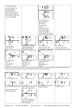
Pictograms installation point of calculator (in the information loops)
On the right in the calculator display in all information loops you will find one of the following two pictograms. The pictogram
indicates in which pipe the calculator is to be mounted.
Installation in outlet flow
Installation in inlet flow
3.4
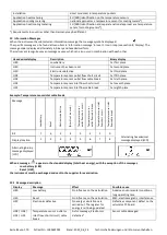
Pictograms type of calculator (on type identification label)
Heat meter calculator
Cooling meter calculator
4
Wall Mounting the Calculator
You can open the calculator by pulling the clamping bracket at the upper housing´s leading edge up.
Before mounting, check to make sure that the cable lengths of the instruments to be connected are correct for the individual
installation situation.
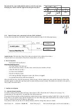
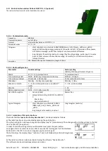
The center to center drill hole separation for the direct screw mounting is in the following picture 131 mm.
With commonly available
mounting rail
Direct screw mounting
5
Connecting the Components
Important:
First mount the temperature sensors and then connect the flow meter to the calculator. This way unnecessary
error messages can be avoided.
At delivery, the display shows „H 05“ until temperature sensors have been attached.
This message disappears as soon as
temperature sensors have been connected and the first temperature measurement is carried out (every 15 minutes without
flow).
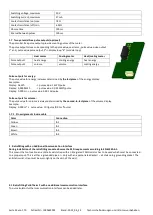
The calculator connections have been designed to meet the valid standard EN1434-2. All terminal strips have been labelled
according to this standard.
The terminal strips are located under the cover of the calculator housing.
5.1
Mounting the temperature sensors
Please note the following points:
-
The temperature sensors must have the type of Pt suitable for the calculator (Pt 500). The calculator identifies the
temperature sensors automatically and shows the type of Pt in loop 2.
-
The temperature sensors (up to DN 100) must be installed against the flow direction.
-
The temperature sensors are not to be installed within the influence of other sources of heat.
-
The temperature sensor cables must not be kinked, lengthened or shortened.


