Seite 79 von 170 Artikel Nr.: 1080622001 Stand: 2022_06_24 Technische Änderungen und Irrtümer vorbehalten.
Please check the unused cable glands to make sure that the necessary
blind plugs are inserted and then tighten the cable glands by hand.
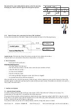
5.2.1 Special features when connecting to a Sensus VMT „PolluFlow“
For the correct connection of the cables, please note the polarity described in the following drawing:
Important note
: The colored marking of the cables corresponds to the scheme shown above.
The white cable (+) is connected to clamp 10, the brown cable (-) to clamp 11.
6
Start of Operation
-
Slowly open the shut-off valves.
Check the following points:
-
Is the flow meter of the right size?
-
Does the directional arrow on the flow meter match the actual direction of flow?
-
Check that there are no leaks.
-
Is a flow volume displayed?
-
Are all shut-off valves open?
-
Is the heating (heating/cooling) system clear (dirt filters not clogged)?
-
Is a plausible temperature difference displayed?
When the components are functioning properly, attach the seals to the temperature sensors and the flow meter. Protect the
calculator against unauthorized opening using the numbered adhesive seal enclosed. The added bar code label can be used for
the purpose of documentation.
7
Interfaces and Options
7.1
Optical (infrared) interface
For communication with the optical interface an optocoupler and the “Device Monitor” software are necessary. The
optocoupler and “Device Monitor” are available as accessory equipment.
The optical infrared interface will be activated by automatically sending a header (according to EN 13757-3). Baud rate: 2400
baud. Then you can communicate with the calculator for 4 seconds. After every valid communication the calculator is open for
another 4 seconds. Afterwards the display is deactivated.
The number of read-outs per day via the optical interface is limited. During daily read-out at least 4
Clamp 10
Clamp 11
white
brown
Useful pulse
Sensus PolluFlow FS


