Heat / Cooling Meters Calculator Unit
PolluTherm can be combined with PolluFlow
Installation and Operating Instructions
MH 6114 INT PolluTherm, Page 5
new seals. With flanges, make sure that the
cross-section of the pipe is not reduced by the
positioning of the seals.
Installation in cooling systems:
It is recommended to install the flow sensor into
the warm pipe (return) of the cooling system.
PolluTherm X (installation into the warm pipe)
must be used in cooling systems. If Sensus flow
sensors are used, note to the approved
temperature range.
5.2 Installation of the Temperature Sensor
PolluTherm is operated using a pair of
temperature sensors, Type Pt 500. The type of
temperature sensors that can be used is given on
the front of the calculator unit.
In accordance with the guideline of the PTB
TR K 9, heat and cooling meters with nominal
flows of
≤
Qp 6m³/h, only direct immersion is
permitted (refer to MID starter kit) (refer to
Figure 6) when installing the temperature
sensor into new installations of the pipeline
section in the area of the measurement
position with nominal pressures of
≤
16 bar,.
Here, our MID starter kit should be used. This
consists of special ball valves with temperature
sensor seat M10 x 1, with integrated union nuts
and an adapter (refer to Datasheet MH 1131 DE).
These starter kits are compatible with the
temperature sensor types L = 45 mm /
ø
= 5.2
mm and DS 27.5. They are supplied up to
R1“(DN 25).
The EN 1434-2 can be used as a general
installation guideline.
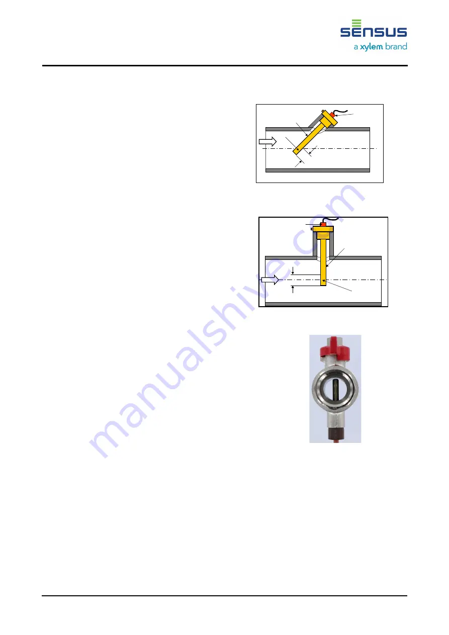
When using Sensus temperature sensors with the
installation lengths of 100 mm and 150 mm, the
active measuring part is measured approx. 10 to
15 mm from the tip of the temperature sensor and
must be located as close as possible to the centre
in the pipeline. For these types, it is
recommended to install as follows:
Nominal diameters
≥
DN 80*: Installation of the
temperature sensor at an angle of 45° against the
direction of flow (refer to Figure 4).
Nominal diameters
≥
DN 65*: Installation of the
temperature sensor vertical to the direction of flow
(refer to Figure 5).
* For DN 65 and DN 80, both installation positions are
permitted, up to DN 50, installation is also possible in the pipe
elbow
For larger nominal diameters (from approx. DN
150) the sleeve must be immersed a minimum of
50 mm into the pipeline.
Figure 4: Exemplary illustration for
Nominal diameter DN 50
Figure 5: Exemplary illustration for
Nominal diameter DN 100
Figure 6: temperature sensor, direct
immersion
5.3 Installation of the Calculator Unit
Use the C-rail with two bolts to attach the
calculator in the horizontal position at the required
position. Place the housing on the C-rail and use
a flat-head screwdriver to raise the red snap-in
hook.
Next, press the housing onto the C-rail and
release the snap-in hook. Alternatively, the
calculator unit can also be directly installed onto
the flow sensor.
Messaktiver Teil
Tauchhülse
Tempera
-
turfühler
ca. 10
-
15 mm
Messaktiver Teil
Tauchhülse
Temperaturfühler
ca. 10-15 mm


