43
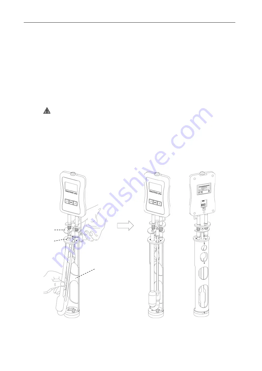
3.4 Place the viscometer into the ViscoClock plus
Press the guidance plate (7) up against the handle plate (9) (see
Fig.
3
).
- The following applies to the use of Ubbelohde and Micro Ubbelohde viscometers:
•
Insert the viscometer sloped through the guidance plate (6), and then insert it vertically into the
centering (2) prism.
> The capillary tube of the viscometer is located underneath the IR light barriers.
•
Lower the guidance plate (7).
•
Check for correct seating of the silicone plug on the fill tube (21) (silicone plug 8D) and capillary
•
The viscometer is now seated.
•
Attach the silicone cap
to the ventilation tube
at a 90° angle
!
With a lateral load on the ventilation tube, the glass tube may break!
- The following applies to Micro Oswald viscometers:
•
Insert the Micro Ostwald viscometer into the stand (3) of the ViscoClock
plus
so that the fill tube is
inserted into the elongated hole of the guidance plate (6).
•
Lower the guidance plate (7).
•
With Micro Ostwald viscometers, the manual pump set "suction" VZ 6554 is required.
Fig. 3 Inserting the viscometer into the ViscoClock plus
Summary of Contents for SI Analytics ViscoClock plus
Page 1: ...OPERATING MANUAL ViscoClock plus VISCOSITY MEASURING DEVICE...
Page 33: ......
Page 34: ......
Page 35: ......


