background image

38 


1.4  Warnings and safety information 

The ViscoClock 

plus

 unit is protected as per protection class III.  

It was manufactured and tested according to DIN EN 61 010  -  1, Part 1, "

Protective Measures for 

electronic measurement devices and control devices

" and has left the factory in an impeccable 

condition as concerns safety technology. In order to maintain this condition and to ensure safe operation, 
the user should observe the notes and warning information contained in the present operating instructions. 
Development and production is done within a system which meets the requirements laid down in the  
DIN EN ISO 9001 standard. 

 Please also note the corresponding Operating instructions for the devices to be connected. 

 For reasons of safety, the device  must only be used for the range of application described in the 

present operating instructions.  Nonobservance of  the intended proper use of the device may result in 
personal injury or damage to property. 

 For reasons of safety, the unit and the power supply TZ 1858 must be opened by authorized persons 

only; this means, for instance, that work on electrical equipment must only be performed by qualified 
specialists. 

In case of nonobservance of these provisions the titrator and the power supply may 

constitute a danger:  electrical accidents and a fire hazard! 

Moreover, in the case of unauthorized 

intervention in the titrator or the power supply, as well as in the case of negligently or deliberately caused 
damage, the warranty will become void.


 Prior to switching on the unit, it has to be ensured that the operating voltage matches the mains 

voltage. The operating voltage is indicated on the type plate (bottom side of the unit and backside of the 
power supply). 

Nonobservance of this provision may result in damage to the unit and the power 

supply, or in personal injury or damage to property! 


If it has to be assumed that safe operation is impossible, the unit has to be taken out of 

operation and secured against inadvertent putting to operation

! For this, switch off the unit, pull plug 

of the mains cable out of the power supply, and remove the meter from the work station. 

Examples for the assumption that a safe operation is no longer possible, 


if the package is damaged, 


if the unit shows visible damages, 


if the power supply TZ 1858 shows visible damages, 


if the unit does not function properly, 


if liquid has penetrated into the casing. 


if the unit has been altered technologically or if unauthorized personnel tried or succeeded to open the 
instrument as attempt to repair it. 


In case that the user operates such a device, all thereof resulting risks are on the user. 

 The unit must not be stored or operated in moist rooms. 

 The relevant regulations regarding the handling of the substances used have to be observed:


The Decree on Hazardous Matters, the Chemicals Act, and the rules and information of the chemicals 
trade. On the part of the user it has to be ensured that the persons entrusted with the use of the unit are 
experts in the handling of substances used in the environment or that they are supervised by specialized 
persons, respectively.  


For all work with chemicals: 

Always


wear protective goggles!

 Please observe the memorandums of 

the employer's liability insurance associations and the safety data sheets of the manufacturers. 


Please observe the standard regulations and Standards for capillary-viscosity measurements!


The manufacturer of the unit has a list of the national and international standards available. 


Always attach the silicone cap


perpendicular


onto the ventilation tube

With a lateral load on 

the ventilation tube, the glass tube may break! 

 Do not pump the sample liquid into the measuring sphere using the manual pump  after 

pressing the start key!

 Sample liquid will enter the unit via the ventilation tube. 

This results in damage 

to the unit


Summary of Contents for SI Analytics ViscoClock plus

Page 1: ...OPERATING MANUAL ViscoClock plus VISCOSITY MEASURING DEVICE...

Page 2: ...92 Instructions importantes Le manuel d utilisation fait partie de l appareil Pri re de lire et d observer attentivement le mode d emploi avant la premi re mise en marche de l appareil et de le conse...

Page 3: ...er TZ 3863 46 3 8 Prepare for measurement 47 3 9 Start measurement 48 3 10 Reading the flow time 49 3 11 Standby and switching off 49 3 12 Viscosity calculation 49 3 13 Evaluation example 50 4 Descrip...

Page 4: ...nother part of the operating manual Status at time of printing Advanced technology and the high quality of our products are guaranteed by a continuous development This may result in differences betwee...

Page 5: ...Clock plus is fixed by the manual measurement insert of the bath and which is suitable for the intended temperature range For tempering in the thermostat tempering range 40 to 150 C the following temp...

Page 6: ...60 Hz Input 9 Volt DC 450 mA Power Input 4 W Corresponds to protective system III protection class for dust and humidity Protection type for dust and moisture IP 50 as per DIN 40 050 Use only the inc...

Page 7: ...eration 8S Silicone plug for capillary tube for suction operation 9 Handle plate 10 Silicone cap for ventilation tube of the viscometer VZ 5101 11 Electronic measuring unit 12 LC graphic display 13 ke...

Page 8: ...nal injury or damage to property If it has to be assumed that safe operation is impossible the unit has to be taken out of operation and secured against inadvertent putting to operation For this switc...

Page 9: ...o a polypropylene casing Owing to the use of heat carrier liquids as bath media color changes may occur on the stand which do not affect the measurement accuracy 2 Unpacking and Setup Check packing to...

Page 10: ...ig 2 Description of the usable viscometer models Use only original SI Analytics viscometers If you are using viscometers by other manufacturers the function of the ViscoClock plus cannot be guaranteed...

Page 11: ...cro Ubbelohde 536 Micro Ubbelohde 538 Micro Ostwald 517 Micro Ostwald 516 Micro Ostwald 518 Table 1 List of viscometers for the selection of viscometers that are suitable to measure the flow time for...

Page 12: ...g i e the sample is filtered from the syringe through the filter If this is not performed correctly there is a risk of the syringe filter detaching itself from the syringe due to the created pressure...

Page 13: ...ating of the silicone plug on the fill tube 21 silicone plug 8D and capillary tube 22 silicone plug 8S The viscometer is now seated Attach the silicone cap 10 to the ventilation tube at a 90 angle Wit...

Page 14: ...ed on the type plate bottom side of the unit and backside of the power supply Nonobservance of this provision may result in damage to the unit and the power supply or in personal injury or damage to p...

Page 15: ...OTG adapter cable VZ6570 Fig 5 Connection of a USB drive to the ViscoClock plus 3 7 2 Connection of the printer TZ 3863 To print the measured data to the printer TZ 3863 this can simply be connected...

Page 16: ...h USB drives and the printer one device is connected to the USB A connector 18 and the other device is connected to the USB Mini B connector 17 via the OTG adapter cable VZ6570 optional accessory Fig...

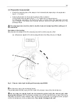
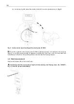
Page 17: ...scometer Description of the handling Manually place the adapter 28 of the manual pump onto the silicone plug 8 either a with pressure applied to the silicone plug 8D above the filling tube see Fig 8 F...

Page 18: ...sory not included in the scope of delivery is recommended especially for aggressive liquids which must never enter the thermostat bath inadvertently Furthermore this operating mode is recommended for...

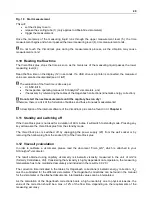
Page 19: ...the ViscoClock plus can be found in Chapter 4 3 11 Standby and switching off If the ViscoClock plus is not used for a duration of 60 minutes it will switch to standby mode Pressing any key will awake...

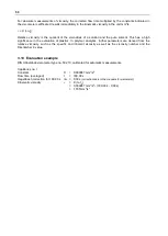
Page 20: ...ation of plastics In polymer analytics further parameters are derived from the relative viscosity such as the specific and inherent viscosity as well as the viscosity number and the Fikentscher K valu...

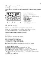
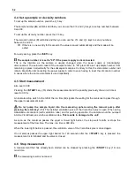
Page 21: ...number increase parameters The following sections will show more information about the different key functions 4 3 Set time activate sounds If you press the SET key for a long time you will be in the...

Page 22: ...t measurement Also see 3 9 Pressing the START key 16 starts the measurement and the possibly previously shown run time is reset to 0 00 s An animated stop watch to the left of the run time A signals t...

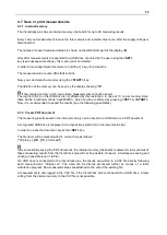
Page 23: ...confirmed by pressing SET or START Now it is recommended to export the results see the following possibilities 4 7 2 Create PDF document The measuring results saved in the internal memory can be save...

Page 24: ...the same time 4 7 5 Documentation format The documentation of the measuring results PDF printout has the following format No Date Time SID VID Flow Time 1 22 08 16 13 43 01 09 176 54 No Consecutive me...

Page 25: ...ck plus can be put into standby mode by pressing the START key early for a long time 4 8 Notes and error messages If an error occurs or if the user is notified of a full memory the ViscoClock plus dis...

Page 26: ...re file e g VCplus_FW_V_16_35 bin directly and without a subdirectory to the USB memory device The file must not be renamed and there must not be any other update file in the same directory 2 Connect...

Page 27: ...meter 5 2 Cleaning After each use you should clean the stand 3 using a moist cloth and e g dishwashing liquid Clean the upper 5 and lower 4 measurement level with a fine dry paintbrush Transmitter and...

Page 28: ...p to the ventilation tube The sample rises in the venting tube when pushed up Cause Remedy Silicone cap 10 is not attached to the ventilation tube of the Ubbelohde viscometer Attach the silicone cap 1...

Page 29: ...ht barrier The timer is not running properly or not running at all Cause Remedy The sample liquid is not transparent enough Check the ViscoClock plus with a transparent specimen Malfunction of the tim...

Page 30: ...ample liquid 2 Sample was not above the upper light barrier at the time of triggering 1 Air bubbles in the sample liquid 2 Pump the sample above the upper light barrier prior to starting the measureme...

Page 31: ...g to host 0x02000E21 0x02000E2B See above errors Error during printing and PDF generation Error code Display message Errors Description Remedy 0x02001001 No USB drive connected No USB drive connected...

Page 32: ...9 Recycling and disposal Please observe the applicable local or national regulations concerning the disposal of waste electrical and electronic equipment The ViscoClock plus and his packaging are man...

Page 33: ......

Page 34: ......

Page 35: ......

Page 36: ...sp cifi es pour le produit sont respect es Certificado del fabricante Certificamos que el aparato arriba mencionado ha sido controlado de acuerdo con la norma DIN EN ISO 9001 secci n 8 2 4 Seguimient...

Reviews: