Commissioning
Alyza IQ PO4
64
ba76201d03
05/2020
3.3.16 Installing the FM/PC filter module and M 1.5 basin holder for filtra-
tion
Installation
instructions
Heed the following notes when installing the filter module:
Mount the filter module so that the plate is in a position vertical to the flow
direction.
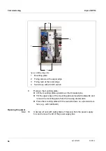
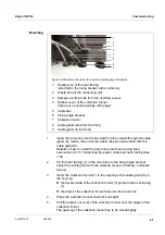
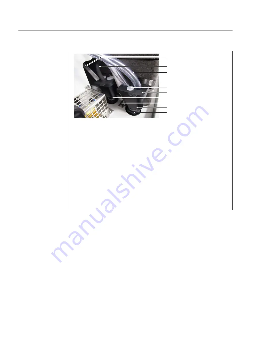
figure 3-26 Collection funnel for the separate discharge of all liquids
1
Heating line of the heat tracing
(attached to the fixing bracket with a cable tie)
2
Waste tube of the measuring unit
3
Sample overflow tube from the overflow vessel
4
Plug for the rubber cover
5
Rubber cover of the collection funnel
(seal unused openings of the rubber cover with plugs)
6
Cable gland (2nd from the front) with collection funnel for chemical
waste
7
Fixing angle bracket
8
Collection funnel
9
Cable gland (front) with collection funnel for sample overflow
10
Position a suitable collecting container (chemical resistant, winterproof)
under the Alyza IQ to collect the chemical waste from the measuring
unit.
11
Fasten the collecting container.
12
Insert the return line of the cable gland (6) into the collecting container.
13
Fasten the return line.
14
Empty the collecting container regularly.
1
2
9
3
5
7
8
6
4
Summary of Contents for WTW Alyza IQ PO4
Page 171: ......


