Installation
DW/P
18
ba77278e01
01/2024
3.2.4 Connecting the IQ S
ENSOR
N
ET
modules
Any modules included in the scope of delivery (e.g. MIQ/IDS) have to be
connected with the IQ S
ENSOR
N
ET
. In most applications, the connection as a
module stack is the simplest way of connecting the IQ S
ENSOR
N
ET
modules.
For details on the connection of IQ S
ENSOR
N
ET
modules, see system operating
manual IQ S
ENSOR
N
ET
.
3.2.5 Preparing the turbidimeter for operation
General information on commissioning (see operating manual of the
turbidimeter).
For initial commissioning:
3.2.6 Connecting the turbidimeter to the MIQ/IC2 module
Measuring instruments that have a current output can be connected to the
IQ S
ENSOR
N
ET
with the MIQ/IC2 module.
6.
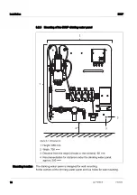
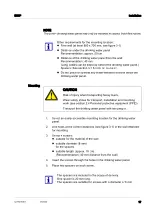
Securely fasten the drinking water panel.
Make sure that the drinking water panel does not bend.
1.
Remove the desiccant pouch from the cell of the turbidimeter and dis
-
pose of it.
2.
Insert the enclosed desiccant pouch into the base of the instrument (see
operating instructions for turbidimeter)
Cables with a diameter of 5.8 mm to 10 mm are suitable for con
-
necting the turbidimeter to the MIQ/IC2 module (see MIQ/IC2 and
turbidimeter operating manuals)
1.
Connect the current output on the turbidimeter to the current input on
the MIQ/IC2 module.
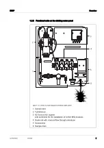
Guide the cable of the power supply through the cable opening of the
drinking water panel.

