Maintenance and cleaning
DW/P
28
ba77278e01
01/2024
4.3
System expansion
4.3.1 IQ S
ENSOR
N
ET
System expansion of the IQ S
ENSOR
N
ET
(see system operating manual of the
IQ S
ENSOR
N
ET
).
4.3.2 Flow through armatures
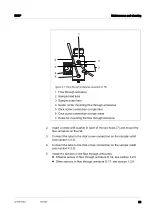
All flow through armatures included in the scope of delivery are mounted on a
rail.
The maximum number of flow through armatures on the rail is 4.
If the maximum number of flow through armatures has not yet been reached,
additional flow through armatures can be mounted on the rail.
Replacing or adding
any flow through
armatures
2.
Screw in the screws on the undersides of the flow through armatures
again.
3.
Install the sensors in the flow armatures
(see section 3.2.8 I
or
see section 3.2.9 I
4.
Check that the inlet and outlet connections are tight on all flow through
armatures.
5.
Open the sample inlet.
To be able to connect 4 IDS sensors to the IQ S
ENSOR
N
ET
the fol
-
lowing requirements must be met:
4 IDS interfaces are available on the IQ S
ENSOR
N
ET
.
The IQ S
ENSOR
N
ET
can indicate 4 sensors in the measured
value display.
1.
Select the position for the new flow through armature.
One criterion for the choice of position is, for example, the
space requirement of a sensor upwards.

