background image

ORP voltage

Multi 9430

44

ba75966e04

04/2015

Criteria for a stable

measured value

The 

Stability control

 function checks whether the measured values are stable 

within the monitored time interval. 

The minimum duration until a measured value is assessed as stable is the 
monitored time interval. The actual duration is mostly longer.

5.1.2 Measuring the relative ORP

To measure the difference of the ORPs of two solutions, you have to define the 
ORP of one solution as the zero point first. 

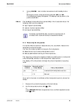
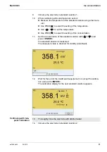
1.

Freeze the measured value with 

<AR>

.

The [HOLD] status indicator is displayed. 
The HOLD function is active.

You can terminate the 

Stability control

 function and the HOLD func-

tion with 

<AR>

 or 

<M>

 at any time. 

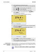
2.

Using 

<ENTER>

, activate the 

Stability control

 function manually.

The [AR] status indicator appears while the measured value is assessed 
as not stable. A progress bar is displayed and the display of the mea-
sured parameter flashes.
As soon as a measured value meets the stability criteria, it is frozen. The 
[HOLD][AR] status indicator is displayed, the progress bar disappears 
and the display of the measured parameter stops flashing. 
The current measurement data is output to the interface. Measurement 
data meeting the stability control criterion is marked by AR.

You can prematurely terminate the 

Stability control

 function manu-

ally with 

<ENTER>

 at any time. When the 

Stability control

 function 

is prematurely terminated, the current measurement data are out-
put to the interface (PC, USB memory device or USB printer) with-
out AutoRead info.

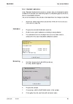
3.

Using 

<ENTER>

, start a further measurement with stability control.

or
Release the frozen measured value again with 

<AR>

 or 

<M>

.

The [AR] status display disappears. The display switches back to the pre-
vious indication. 

Measured 
parameter

Time interval

Stability in the time 
interval

ORP

15 seconds

 : Better than 0.3 mV

Temperature

15 seconds

 : Better than 0.5 °C

Summary of Contents for WTW Multi 9430

Page 1: ...OPERATING MANUAL ba75966e04 04 2015 Multi 9430 DIGITAL METER FOR IDS SENSORS...

Page 2: ...right Weilheim 2015 WTW GmbH Reproduction in whole or even in part is prohibited without the express written permission of WTW GmbH Weilheim Printed in Germany For the most recent version of the manua...

Page 3: ...nauthorized use 11 3 Commissioning 12 3 1 Scope of delivery 12 3 2 Power supply 12 3 3 Initial commissioning 12 3 3 1 Connecting the power pack 13 3 4 General operating principles 14 3 4 1 Keypad 14 3...

Page 4: ...n concentration 47 6 1 Measuring 47 6 1 1 Measuring the ion concentration 47 6 1 2 Measuring the temperature 49 6 2 Calibration 50 6 2 1 Why calibrate 50 6 2 2 When to calibrate 50 6 2 3 Calibration I...

Page 5: ...measurement settings 89 9 4 D O measurement settings 92 9 4 1 Settings for D O measurement 92 9 5 Cond measurement settings 92 9 5 1 Settings for IDS conductivity sensors 92 9 6 Sensor independent se...

Page 6: ...111 12 1 1 General maintenance activities 111 12 1 2 Exchanging the battery 111 12 2 Cleaning 112 12 3 Packing 112 12 4 Disposal 112 13 What to do if 114 13 1 pH 114 13 2 ISE 116 13 3 Dissolved oxyge...

Page 7: ...all applications The Multi 9430 supports you in your work with the following functions proven calibration procedures automatic stability control AR automatic sensor recognition CMC continuous measure...

Page 8: ...data from IDS sensors IDS sensors transmit the following sensor data to the meter SENSOR ID Sensor name Sensor series number Calibration data Measurement settings The calibration data are updated in...

Page 9: ...nus automatically that do not concern this sensor To be able to use the automatic sensor recognition a meter that supports the automatic sensor recognition e g Multi 9430 and a digital IDS sensor are...

Page 10: ...the meter Note all labels information signs and safety symbols on the meter A warning symbol triangle without text refers to safety information in this operating manual 2 1 3 Further documents provid...

Page 11: ...The meter may only be operated according to the authorized use specified above The meter may only be supplied with power by the energy sources mentioned in this operating manual The meter may only be...

Page 12: ...ion with the supplied power pack Operation of the system clock with a buffer battery if there is no mains power supply see section 12 1 2 EXCHANGING THE BATTERY page 111 3 3 Initial commissioning Perf...

Page 13: ...ut voltage range of the original power pack see section 14 2 GENERAL DATA page 120 CAUTION Use original power packs only see section 14 2 GENERAL DATA page 120 1 Connect the plug of the power pack to...

Page 14: ...or off M Selects the measured parameter CAL CAL_ Calls up the calibration procedure Displays the calibration data AR Freezes the measured value HOLD function Switches the AutoRead measurement on or of...

Page 15: ...Info TEC AutoCal e g TEC Calibration with automatic buffer recognition e g with the buffer set Tech nical buffers ConCal Calibration with any buffers Error An error occurred during calibration AR Sta...

Page 16: ...pack 5 Service interface 6 Cover plate The cover plate closes the mounting slot for the IDS adapter ADA 94 IDS DIN or ADA 94 IDS BNC available as an accessory CAUTION Only connect sensors to the mete...

Page 17: ...a connected sensor at any time The sensor data are available in the measured value dis play with the Info softkey 1 Channel display Display of the plug position for the respective parameter The red b...

Page 18: ...ensors With the softkey you can very easily switch between the two display types The suitable softkey is displayed depending on the operating situation 2 Display further sensor data settings with More...

Page 19: ...for the login to the meter If the Password menu item is grayed out no password is required for the login 1 Switch the meter on with On Off The meter performs a self test 2 Connect the sensor The mete...

Page 20: ...e or she first logs in with a user name A valid password consists of 4 digits The user can change the password with the next login 5 Change the digit of the highlighted position with Switch to the nex...

Page 21: ...settings and dialogs in procedures contain further subelements 5 In the Password field enter the old password with and and confirm it with ENTER 6 In the New password field enter the new password with...

Page 22: ...ently the setting can be changed with and ENTER Example Functions Functions are designated by the name of the function They are immediately carried out by confirming with ENTER Example Display the Cal...

Page 23: ...red value display appears The instrument is in the measuring mode 2 Open the Storage config menu with ENTER_ The instrument is in the setting mode Calibration record Calibration data storage Buffer TE...

Page 24: ...6 Open the General submenu with ENTER 7 Open the setting mode for the Language with ENTER 8 Select the required language with General Interface Clock function Service information Reset System 01 08 20...

Page 25: ...itched from the display of day month year dd mm yy to the display of month day year mm dd yy or mm dd yy 9 Confirm the setting with ENTER The meter switches to the measuring mode The selected language...

Page 26: ...nge and confirm the setting with and ENTER The time is set 7 If necessary set the Date and Date format The setting is made simi larly to that of the time 8 To make further settings switch to the next...

Page 27: ...UTOMATIC STABILITY CON TROL page 96 in the System menu The sensor connection and the USB B device interface are gal vanically isolated This facilitates interference free measurements also in the follo...

Page 28: ...pears while the measured value is assessed as not stable A progress bar is displayed and the display of the mea sured parameter flashes As soon as a measured value meets the stability criteria it is f...

Page 29: ...section 9 1 1 SETTINGS FOR PH MEASUREMENTS page 84 Use one to five buffer solutions of the selected buffer set in any order Below calibration with Technical buffers TEC is described When other buffer...

Page 30: ...is displayed The measured parameter flashes 8 Wait for the end of the measurement with stability control or accept the calibration value with ENTER The calibration display for the next buffer appears...

Page 31: ...stability control and take over the calibration value with ENTER The calibration display for the next buffer appears voltage display 15 If necessary finish the calibration procedure as a two point cal...

Page 32: ...d is displayed or Switch to calibration with the next buffer with ENTER Calibration is automatically completed after the last buffer of a buf fer set has been measured Then the calibration record is d...

Page 33: ...e of the buffer with 7 Start the measurement with ENTER The measured value is checked for stability stability control The AR status indicator is displayed The measured parameter flashes 8 Wait for the...

Page 34: ...or in buffer solution 2 14 When measuring without temperature sensor Enter the temperature of the buffer with 15 Start the measurement with ENTER The measured value is checked for stability stability...

Page 35: ...ity control The AR status indicator is displayed The measured parameter flashes 24 Wait for the measurement with stability control to be completed or ter minate the stability control and take over the...

Page 36: ...ration data storage Display To open the Calibration menu press the ENTER key in the measured value display Calibration Determined val ues Displayed calibration data 1 point Asy Zero point Asy Slope Ne...

Page 37: ...libration record to the USB B PC interface or the USB A USB printer interface Using PRT_ output all calibra tion records to the USB B PC interface or the USB A USB printer interface Quit the display w...

Page 38: ...e measuring range Clean the IDS sensor according to the sensor operating manual Error Error 30 or 30 62 0 or 50 0 Error elimination see section 13 WHAT TO DO IF page 114 For pH IDS sensors you can opt...

Page 39: ...for documentation 4 Measuring range for which no valid calibration is available dark gray Measured values in this range are not suitable for documenta tion Calibrate the meter with buffers covering th...

Page 40: ...pecial QSC buffer solutions It covers the measuring range of the sensor pH 2 to pH 11 The QSC initial calibration determines the actual condi tion of the sensor and stores it as a reference in the sen...

Page 41: ...ble to return to the sensor evaluation with the sensor symbol for this sensor 1 Open the menu for measurement settings with ENTER 2 In the QSC menu select First calibration with The calibration displa...

Page 42: ...ion 01 08 2013 08 00 Info 1 1 Open the menu for measurement settings with ENTER 2 In the QSC menu select Control calibration with The calibration display appears AutoCal QSC Kit is displayed as the bu...

Page 43: ...ic Stability control see section 9 6 3 AUTOMATIC STABILITY CONTROL page 96 in the System menu The sensor connection and the USB B device interface are gal vanically isolated This facilitates interfere...

Page 44: ...e A progress bar is displayed and the display of the mea sured parameter flashes As soon as a measured value meets the stability criteria it is frozen The HOLD AR status indicator is displayed the pro...

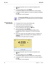
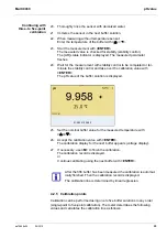
Page 45: ...5 Display the potential of the current zero point with CAL 6 Press ENTER to measure the reference solution The measured value is checked for stability automatic stability con trol The display of the m...

Page 46: ...easuring instrument recognizes whether a suitable sensor is connected and automatically switches on the temperature measurement The display of the temperature indicates the active temperature measurin...

Page 47: ...rement and calibration should not be greater that 2 K Therefore adjust the temperature of the standard and measuring solutions accordingly If the temperature difference is greater the TpErr warning ap...

Page 48: ...is active You can terminate the Stability control function and the HOLD func tion with AR or M at any time 2 Using ENTER activate the Stability control function manually The AR status indicator appear...

Page 49: ...and automatically switches on the temperature measurement The display of the temperature indicates the active temperature measuring mode If you wish to measure or calibrate without temperature sensor...

Page 50: ...rocedure that uses 2 to 7 freely selectable standard solutions The concentration expected for the measurement determines the concentration of the calibration standards 1 Connect the ISE combination el...

Page 51: ...mperature Use F4 to select the setting of the concentration 11 Set the concentration of the standard solution with and press ENTER The standard solution is measured The measured value is checked for s...

Page 52: ...ect the setting of the concentration 16 Set the concentration of the standard solution with and press ENTER The standard solution is measured The measured value is checked for stability AutoRead 17 Wa...

Page 53: ...storage Display To open the Calibration menu press the ENTER key in the measured value display Select the unit of the standard solution and measurement result in the ISE setup Unit menu Standard solut...

Page 54: ...Using PRT_ output all calibra tion records to the USB B PC interface or the USB A USB printer interface Quit the display with ESC Switch directly to the measured value display with M Calibration Calib...

Page 55: ...Multi 9430 Ser no 12345678 CALIBRATION ISE 18 01 2013 08 09 10 Sensor Ser no 12345678 Standard 1 0 010 mg l Standard 2 0 020 mg l Voltage 1 38 5 mV Voltage 2 58 0 mV Temperature 1 24 0 C Temperature 2...

Page 56: ...of the test sample with a ther mometer 4 Open the ISE menu with ENTER 5 Thoroughly rinse the electrode with distilled water 6 Adjust the temperature of the standard solutions 7 Select Method with and...

Page 57: ...value is achieved for the second standard calibration solution 01 08 2013 08 00 01 08 2013 08 00 1 0 010 mg l 20 2 mV 25 0 C 2 0 020 mg l 79 2 mV 25 0 C Slp 54 1 mV Sensor Ion type Ag CALIBRATION ADA...

Page 58: ...solu tion Std conc 14 Select continue with and start the measurement with ENTER The measurement result is displayed when the measurement is com pleted 15 If necessary start measuring further samples w...

Page 59: ...ration solutions 3 Perform a two point calibration according to user guidance 4 The calibration record is displayed as soon as a stable value is achieved for the second standard calibration solution 0...

Page 60: ...lution Std volume and concentration of the standard solu tion Std conc 14 If necessary set the ion type for the ion in the standard Ion type with and ENTER On selection of the ion type that can be def...

Page 61: ...9430 Ion concentration ba75966e04 04 2015 61 17 Terminate the measuring method with M A safety query appears 18 Select yes with 19 Confirm yes with ENTER Measurement with the selected method is compl...

Page 62: ...calibration record is displayed as soon as a stable value is achieved for the second standard calibration solution 01 08 2013 08 00 01 08 2013 08 00 1 0 010 mg l 20 2 mV 25 0 C 2 0 020 mg l 79 2 mV 2...

Page 63: ...standard solution 13 Using and ENTER enter the value for the volume of the sample Sample volume 14 Select continue with and start the measurement with ENTER The measurement result is displayed when th...

Page 64: ...HOD page 56 2 If necessary set the ion type for the ion in the standard Ion type with and ENTER On selection of the ion type that can be defined ION Using and ENTER set the valence Valency and molar w...

Page 65: ...d solu tion Std conc and the volume of the ISA TISAB solution ISA TISAB vol 13 Select continue with and start the measurement with ENTER When the measurement is finished an entry window appears 14 Add...

Page 66: ...sample is calculated from the change in potential Calibration 17 If necessary start measuring further samples with ENTER Repeat steps 8 16 for all samples 18 Terminate the measuring method with M A sa...

Page 67: ...zed water 9 Immerse the electrode in the sample that was supplemented with blank value solution 10 Using and ENTER enter the values for the volume of the sample Sample volume the volume of the ISA TIS...

Page 68: ...ement with ENTER The measurement result is displayed when the measure ment is completed 15 If necessary start measuring further samples with ENTER Repeat steps 6 14 for all samples 16 Terminate the me...

Page 69: ...ity of the measured medium first When the salinity correction is switched on the Sal indicator is displayed in the measuring screen 1 Connect the IDS D O sensor to the meter The D O measuring screen i...

Page 70: ...ty control manually at any time 1 Freeze the measured value with AR The HOLD status indicator is displayed The HOLD function is active You can terminate the Stability control function and the HOLD fun...

Page 71: ...manner whether the FDO 925 D O sensor should be cleaned or calibrated 7 2 2 When should you check the sensor Checking can be useful in the following cases When the check interval has expired the check...

Page 72: ...e check and storage beaker FDO Check The sponge in the check and storage beaker must be moist not wet Leave the sensor in the check and storage beaker long enough so it can adapt to the ambient temper...

Page 73: ...7 3 2 When to calibrate If your evaluation of the FDO Check procedure suggests the necessity of a calibration When the calibration interval has expired When your accuracy requirements are especially...

Page 74: ...the check and storage bea ker FDO Check The sponge in the check and storage beaker must be moist not wet Leave the sensor in the check and storage beaker long enough so it can adapt to the ambient te...

Page 75: ...he measured value is checked for stability stability control The AR status indicator is displayed The measured parameter flashes 5 Wait for the end of the AutoRead measurement or accept the calibratio...

Page 76: ...tion record The calibration record is automatically transmitted to the interface after calibrating Menu item Setting func tion Explanation Calibration Calibration data storage Display Displays the cal...

Page 77: ...rd Display Calibration record Relative slope S 0 94 1 06 S 0 92 0 94 or S 1 06 1 08 S 0 90 0 92 or S 1 08 1 10 Error Error S 0 90 or S 1 10 Error elimination see section 13 WHAT TO DO IF page 114 CALI...

Page 78: ...The stability has a considerable impact on the reproduc ibility of measured values The measured parameter flashes on the display as soon as the measured value is outside the stability range when the...

Page 79: ...not stable A progress bar is displayed and the display of the measured parameter flashes As soon as a measured value meets the stability criteria it is frozen The HOLD AR status indicator is displayed...

Page 80: ...o ISO 7888 Linear temperature compensation lin with adjustable coefficients of 0 000 3 000 K No temperature compensation off Application tips Select the following temperature compensations given in th...

Page 81: ...cell constant calibration in control standard You can determine the actual cell constant of the IDS conductivity sensor by calibrating with the control standard in the following range 0 450 0 500 cm...

Page 82: ...s checked for stability stability control The AR status indicator is displayed The measured parameter flashes 6 Wait for the end of the measurement with stability control or take over the calibrated v...

Page 83: ...s the stored calibration data to the USB A interface USB mem ory device USB printer Calibration Calibration data storage Output to RS232 USB Outputs the stored calibration data to the USB B interface...

Page 84: ...erface USB memory device USB printer Calibration Buffer TEC ConCal NIST DIN Buffer sets to be used for pH calibration More buffers and details see section 9 1 2 BUFFER SETS FOR CALIBRATION page 86 and...

Page 85: ...signal in the System menu see section 9 6 1 SYSTEM page 95 Limit monitoring pH monitoring on off Switch on or off the limit signaling device for the pH value Limit monitoring TP monitoring on off Swit...

Page 86: ...elivery condition see section 9 7 1 RESETTING THE MEASUREMENT SETTINGS page 97 Menu item Possible setting Explanation No Buffer set pH values at 1 ConCal Any Any 2 NIST DIN DIN buffers according to DI...

Page 87: ...13 Fluka BS 4 006 6 984 8 957 25 C 14 Radiometer 1 678 4 005 7 000 9 180 25 C 15 Baker 4 006 6 991 10 008 25 C 16 Metrohm 3 996 7 003 8 999 25 C 17 Beckman 4 005 7 005 10 013 25 C 18 Hamilton Duracal...

Page 88: ...bra tion interval The calibration interval is set to 7 days in the factory You can change the interval 1 999 days 22 Reagecon 25 2 000 4 000 7 000 10 000 13 000 25 C 23 Chemsolute 2 000 4 000 7 000 10...

Page 89: ...easuring menu of the ISE measurement To open the settings activate the relevant measuring window in the measured value display and press the ENTER key shortly After completing the set tings switch to...

Page 90: ...ords to the interface Man temperature 25 25 130 C Entry of the manually deter mined temperature For measurements without tem perature sensor only Alternative tempera ture on off Takes the measured tem...

Page 91: ...mg l mol l mg kg ppm Selection with which unit the measurement result and calibration standards should be displayed ISE setup Valency 8 8 Set the valence Valency and molar weight Molar mass for the i...

Page 92: ...possible settings are individually displayed for each sensor Below the set ting menu is displayed for two IDS sensors TetraCon 925 LR 925 01 Default settings are printed in bold Setting menu of Tetra...

Page 93: ...Procedure for temperature compen sation see section 8 2 TEMPERATURE COMPENSATION page 80 This setting is only available for the measured parameters and Temp comp TC Linear coeff 0 000 2 000 3 000 K Co...

Page 94: ...ng is only available for the measured parameters and Temp comp TC Linear coeff 0 000 2 000 3 000 K Coefficient of the linear temperature compensation This menu item is only available when the linear t...

Page 95: ...ty control on off Switches on or off the automatic sta bility control during measurement see section 9 6 3 AUTOMATIC STABI LITY CONTROL page 96 System Interface Baud rate 1200 2400 4800 9600 19200 Bau...

Page 96: ...iderable impact on the reproducibility of measured values You can activate or switch off the automatic Stability control function see section 9 6 SENSOR INDEPENDENT SETTINGS page 95 The measured param...

Page 97: ...llowing settings for ORP measurements are reset to the default settings with the Reset function The sensor settings are reset under the Reset menu item in the menu for cali bration and measurement set...

Page 98: ...surement settings To open the settings display the required measured parameter in the measured value display and press the ENTER key Conductivity The following settings for conductivity measurements a...

Page 99: ...u for cali bration and measurement settings To open the settings display the required measured parameter in the measured value display and press the ENTER key Reference temperature 25 C Temperature co...

Page 100: ...ndition The system settings are reset in the menu Storage config System Reset To open the Storage config menu press the ENTER_ key in the measured value display Setting Default settings Language Engli...

Page 101: ...ection 10 3 1 EDITING THE MEASUREMENT DATA STORAGE page 104 and sub sequently erase the storage see section 10 3 2 ERASING THE MEASUREMENT DATA STORAGE page 105 10 2 Automatic data storage at interval...

Page 102: ...Possible setting Explanation ID number 1 10000 ID number for the dataset series Interval 1 s 5 s 10 s 30 s 1 min 5 min 10 min 15 min 30 min 60 min Storage interval The lower limit of the storage inter...

Page 103: ...to switch off the automatic data storage function before the adjusted storage duration has expired 1 Remaining storage duration 2 Graphical display of the storage duration If the automatic data stora...

Page 104: ...data storage as an example The same settings and functions are available for the automatic data storage Menu item Setting function Explanation Data storage Manual data storage Display Displays all mea...

Page 105: ...on 10 3 1 EDITING THE MEASUREMENT DATA STORAGE page 104 10 3 3 Measurement dataset A complete dataset includes Date time Meter name series number Sensor name series number ID number Manual data storag...

Page 106: ...e storing stable measured value Otherwise the AR dis play is missing Calibration evaluation 4 levels or no evaluation or QSC percentage 10 3 4 Storage locations The Multi 9430 meter has two measuremen...

Page 107: ...rface USB Device Connect the Multi 9430 to the PC via the USB B interface Installation of the USB driver on the PC System requirements of the PC for installation of the USB driver PC with at least one...

Page 108: ...rate to be selected in the range 1200 19200 Handshake RTS CTS Set at the PC only Parity none Data bits 8 Stop bits 2 1 Connect a USB memory device USB printer to the USB Host interface Model Type Pape...

Page 109: ...ge process see section 10 2 AUTOMATIC DATA STORAGE AT INTERVALS page 101 Stored mea sured values Manual Displayed dataset with PRT after calling up from the storage All datasets with the Output to RS2...

Page 110: ...Importer software you can record and evaluate measurement data with a PC With the aid of the BOD Analyst Pro software you can administrate BOD measurement on the PC and automatically calculate the me...

Page 111: ...of a power failure See the relevant operating manuals of the IDS sensors for instruc tions on maintenance To retain the current setting of the date and time during the battery exchange supply the met...

Page 112: ...e the battery from the battery compartment 4 Insert a new battery in the battery compartment 5 Close the battery compartment 1 The date day flashes on the display 6 Tighten the screws 2 of the lid of...

Page 113: ...Multi 9430 Maintenance cleaning disposal ba75966e04 04 2015 113...

Page 114: ...he diaphragm Extract air or moisten junction Cable broken Exchange IDS pH sensor Gel electrolyte dried out Exchange IDS pH sensor Cause Remedy IDS pH sensor The values determined for zero point and sl...

Page 115: ...essary Temperature not stable Adjust temperature if necessary IDS pH sensor test sample Conductivity too low Use suitable IDS pH sensor Temperature too high Use suitable IDS pH sensor Organic liquids...

Page 116: ...e electrode Electrode not suitable for the selected ion Use a suitable electrode or select a suitable ion The gas sensitive electrode NH 500 was calibrated with the NH4 setting Select the following se...

Page 117: ...Sensor contaminated Clean the sensor Measured temperature value outside the operating conditions display of OFL UFL instead of a temperature value Keep to the temperature range for the test sample De...

Page 118: ...by the service department Switch on the meter Open the menu ENTER_ Storage config System Ser vice information The instrument data are displayed or Connect the sensor Press softkey Info More The senso...

Page 119: ...m the USB B interface Use a suitable USB printer see section 11 4 CONNECTING A USB MEMORY DEVICE USB PRINTER USB A INTERFACE USB HOST page 108 Check printer settings see sec tion 11 4 CONNECTING A USB...

Page 120: ...rotective class III Test certificates CE cETLus Ambient conditions Storage 25 C 65 C Operation 0 C 40 C Admissible relative humidity Yearly mean 75 30 days year 95 Other days 85 Power supply Power pac...

Page 121: ...ice pursuant to Part 15 of the FCC Rules These limits are designed to provide reasonable protection against harmful interference when the equipment is operated in a commercial environment This equipme...

Page 122: ...x x Pseudomonas aeruginosa 99 1 Reduction After 24 Hours x x Streptococcus faecalis 99 4 Reduction After 24 Hours x x Phoma violacea 99 0 Reduction After 48 Hours x x Penicillium purpurogenum 99 3 Re...

Page 123: ...Desc Job Ref 05B1760 x x x Test Result Unit Est Staphylococcus aureus 99 0 Reduction After 24 Hours x x x Escherichia coli 0157 99 8 Reduction After 24 Hours x x x Aspergillus niger 99 1 Reduction Af...

Page 124: ...VERSION IS IN THE METER OR IDS SENSOR PAGE 118 1 Install the downloaded firmware update on a PC An update folder is created in the Windows start menu If an update folder already exists for the meter...

Page 125: ...date on a PC An update folder is created in the Windows start menu If an update folder already exists for the sensor or sensor type the new data are displayed there 2 In the windows start menu open th...

Page 126: ...n ions activity divided by the unit of the molality The practical pH value is the value of a pH measurement Potentiometry Name of a measuring technique The signal depending on the mea sured parameter...

Page 127: ...ple but the measured value is not converted TRef Meas 1 1 a T TRef D O partial pressure Pressure caused by the oxygen in a gas mixture or liquid D O saturation Short name for the relative D O saturati...

Page 128: ...olality is the quantity in Mol of a dissolved substance in 1000 g sol vent Reset Restoring the original condition of all settings of a measuring system Resolution Smallest difference between two measu...

Page 129: ...Firmware update 124 I Initial commissioning 12 Initialize 97 Instrument connectors 16 Interval for calibration 88 K Keys 14 M Measured value display 21 Measurement accuracy 88 Measurement data storage...

Page 130: ...interval 101 Storing in memory 101 Automatic 101 Manual 101 T Temperature compensation 80 Temperature measurement Conductivity 80 ISE 49 O2 71 pH 28 46 Three point calibration ISE 52 pH 31 35 Transmit...

Page 131: ......

Page 132: ...water needs Developing new technologies that will improve the way water is used conserved and re used in the future is central to our work We move treat analyze and return water to the environment and...

Reviews: