8-6
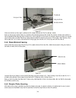
Sipper pump seal replacement
Figure 8-4
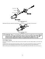
Reassemble the pump, position the plunger as shown in Figure 8-5 and install it back on the instrument.
Sipper pump plunger position
Figure 8-5
WARNING: When re-installing the pump head assembly, the plunger MUST
extend at least 1/2
″
from the base of the pump (see Figure 8-5). This will
assure proper alignment between the pump head and the drive hub.
8.4.5 Bottle Tubing
Disconnect the tubing and unscrew the cable connectors from the buffer, waste and calibrator bottles on each side of the
instrument.
Lift the bottle tray on the right side of the instrument up and remove it. Remove the bottles from the tray and clean the
bottles and caps with the appropriate disinfecting agent (see 8.1 Cleaning, Disinfecting, and Decontaminating).
Remove the two hex screws holding the pump cover on the right side of the instrument. Lift the cover up and remove it.
SPACER
RED O-RING
RED O-RING
Summary of Contents for YSI 2500
Page 1: ...USER MANUAL 525021 YSI 2500 Biochemistry Analyzer OPERATIONS AND MAINTENANCE MANUAL...
Page 34: ...5 11 8 The Stat sample results are displayed on the Run Stat tab Stat sample results...
Page 88: ...13 1 13 Notices Declaration of Conformity 13 1...
Page 96: ...17 1 17 Appendix D Line Power Cord and Plug Wiring United Kingdom United States Europe...

