Installation
System 182-XT-4
3 - 20
ba76027e02
12/2014
3.4.5
Connecting IQ sensors
Sensors can be connected to all free SENSORNET connectors in the
System 182 XT-4. The DIQ/S 182-XT-4-PR has three SENSORNET
connections. If no more free SENSORNET connections are available,
other sensors with the DIQ/JB branching module can be connected
(see section 3.6 and installation examples in section 3.11).
General installation
instructions
Observe the following points when attaching sensors to the system:
The sum of all IQ S
ENSOR
N
ET
line lengths (SNCIQ, SNCIQ/UG and
SACIQ) in the system may be up to a maximum of 250.
IQ S
ENSOR
N
ET
lines must always be installed separately at a
minimum distance of 20 cm from other lines that carry a voltage
greater than 60 V.
Materials required
1 x SACIQ connection cable (see chapter 11 A
)
1 x cable gland, matched to the cable diameter (see section 3.7 on
page 3-31).
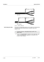
The free end of the connection cable already has the sheath removed
in the factory and all the wires are fitted with wire end sleeves.
Tools
Phillips screwdriver
Small screwdriver.
Connect SACIQ cable to
the
DIQ/S 182-XT-4-PR or
MIQ module
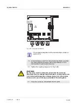
The connection of the SACIQ cable to the terminal strip is described in
section 3.4.4 (see C
NOTE
The SACIQ sensor connection cable may only be connected to the
SENSORNET connections. No wires of the cable may be connected
with an external electrical potential. Otherwise, malfunctions could oc
-
cur.
Connecting the sensor
to the connection cable
1
Remove the protective caps from the plug connections of the
IQ sensor and SACIQ sensor connection cable and keep them
safe.
2
Plug the socket of the SACIQ sensor connection cable onto the
plug head connector of the IQ sensor. At the same time, rotate
the socket so that the pin in the plug head connector (1) clicks
into one of the two holes in the socket.
Summary of Contents for YSI DIQ/S 182-XT-4-PR
Page 6: ...Contents System 182 XT 4 0 4 ba76027e02 12 2014...
Page 10: ...Overview System 182 XT 4 1 4 ba76027e02 12 2014...
Page 14: ...Safety System 182 XT 4 2 4 ba76027e02 12 2014...
Page 64: ...Installation System 182 XT 4 3 50 ba76027e02 12 2014...
Page 82: ...Operation System 182 XT 4 4 18 ba76027e02 12 2014...
Page 88: ...The SETTINGS menu System 182 XT 4 5 6 ba76027e02 12 2014...
Page 114: ...Relay outputs System 182 XT 4 6 26 ba76027e02 12 2014...
Page 116: ...Maintenance and cleaning System 182 XT 4 7 2 ba76027e02 12 2014...
Page 122: ...What to do if System 182 XT 4 8 6 ba76027e02 12 2014...
Page 134: ...Technical data System 182 XT 4 9 12 ba76027e02 12 2014...
Page 135: ...System 182 XT 4 1 ba76027e02 12 2014...
Page 138: ...Accessories and options System 182 XT 4 11 2 ba76027e02 12 2014...
Page 142: ...Appendix store separately if required System 182 XT 4 13 2 ba76027e02 12 2014...
Page 143: ......


