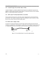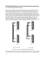
I/O and Cabling Considerations
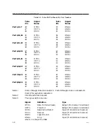
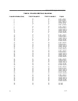
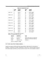
Table 3-1. Telco 50-Pin Pinout, By Port Number
Telco
Signal
Telco
Signal
Pin
Name
Pin
Name
Port 1, 9, 17
28
DTRn
03
RNGn
27
XMTn
02
GNDn
26
RCVn
01
DCDn
Port 2, 10, 18
31
DTRn
06
RNGn
30
XMTn
05
GNDn
29
RCVn
04
DCDn
Port 3, 11, 19
34
DTRn
09
RNGn
33
XMTn
08
GNDn
32
RCVn
07
DCDn
Port 4, 12, 20
37
DTRn
12
RNGn
36
XMTn
11
GNDn
35
RCVn
10
DCDn
Port 5, 13, 21
40
DTRn
15
RNGn
39
XMTn
14
GNDn
38
RCVn
13
DCDn
Port 6, 14, 22
43
DTRn
18
RNGn
42
XMTn
17
GNDn
41
RCVn
16
DCDn
Port 7, 15, 23
46
DTRn
21
RNGn
45
XMTn
20
GNDn
44
RCVn
19
DCDn
Port 8, 16, 24
49
DTRn
24
RNGn
48
XMTn
23
GNDn
47
RCVn
22
DCDn
Note 1:
Ports 1 through 8 are on connector A. Ports 9 through 16 are on connector B.
Ports 17 through 24 on connector C.
Note 2:
Pins 25 and 50 are not used.
Note 3:
The signal definitions are:
Signal
Definition
Type
DTRn
Data Terminal Ready
Output (From server to terminal)
XMTn
Transmit
Output (From server to terminal)
DCDn
Data Carrier Detect
Input (From terminal to server)
RCVn
Receive
Input (From terminal to server)
GNDn
Logic Ground
Common
RNGn
Ring
Input (From terminal to server)
where: n is the port number.
3-32
0021

