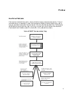
Installation Notes
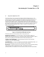
Memory Card Slot
TERMINAL SERVER 720
ETHERNET
CARD RUN CON
C
Serial Port
Status Lights
Ethernet Segment
Indicator Lights
Memory Card Drive Status Light
720 Card Status Light
Console Port Status Light
Reset Switch
.....................................................................................................................................................
2
3
4
5
6
7
1
8
A
B
Memory Card Eject Button
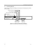
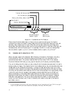
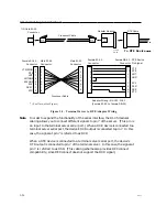
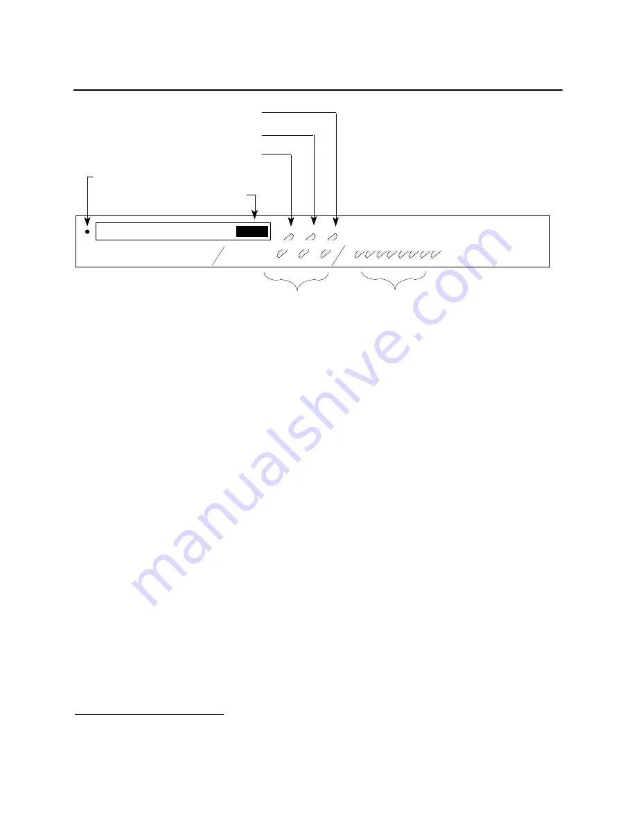
Figure 2-2. Terminal Server 720 Controls.
The serial port status lights shown in Figure 2-2 are used in several ways. During the
initialization process, the lights indicate that self-tests are being performed, and if any self-
test fails, they indicate an error code. After the unit has been received a load image and
parameters, the lights indicate when a port is actively being used. In this case, each light can
indicate activity for more than one port. For example, if LED 1 is lit, this can indicate that
there is activity on ports 1, 9, or 17. LED 2 indicates activity on ports 2, 10, or 18, etc.
1
2.6
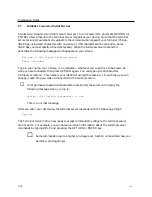
Initialize the Terminal Server 720
When you apply power to the Network 9000 Chassis, all modules in the chassis, including
Terminal Server 720 units initialize themselves and begin to try to load software and
operational parameters. If you have installed the Terminal Server 720 into an already
functional Network 9000 Hub, you may need to reset the unit manually, as described below.
The unit is configured at the factory to use a default set of initialization parameters in order to
obtain a software image. This means that, for most configurations, the unit should be able to be
loaded without any configuration changes. Loading is made particularly easy if you have
inserted a memory card which contains the appropriate load image into the Memory Card Slot,
since the unit will load from the memory card. If a card is not present or the appropriate image
is not on the card, the unit requests to be loaded by a host system that has the TCP/IP-LAT
software installed, or a Network 9000 module that has a Memory card which contains the
appropriate load image. (By default, network load requests are transmitted on midplane
Ethernet LAN segment A.) The unit is also configured at the factory to store parameters
locally on a flash memory card, if one is installed, and remotely at properly configured
parameter servers.
1
Each LED indicates port activity on the same numbered port (ports 1 through 8 are shown by LEDs 1 through 8,
respectively) and those ports whose numbers are multiples of 8 added to the LED number
0021
2-17


