Chapter 3
I/O and Cabling Considerations
3.1
Overview to Cabling
There are various serial I/O and cabling schemes available for the Terminal Server 720.
-
The model 723 twenty-port I/O module. Twenty RJ-45 connectors provide connections for
twenty serial devices using modular cabling. These ports support concurrent hardware
and software flow control, at communication speeds from 75 bps to 115.2 Kbps. Section 3.2
covers cabling options for this I/O module.
-
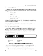
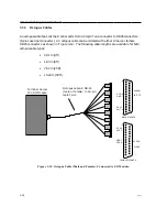
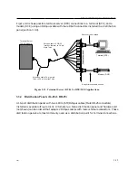
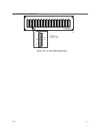
The model 721 sixteen-port I/O module. Two 50-pin TELCO connectors provide
connections for sixteen serial devices, using a variety of wiring schemes, such as
extension cables, distribution panels. splitters, octopus cables, punch-down blocks,
modular (MODtap™) cabling, and DECconnect™ cabling. These ports support modem
control (but not concurrent hardware and software flow control) at communication
speeds from 300 bps to 115.2 Kbps. Section 3.3 covers cabling options for this I/O module.
-
Model 724 24-port I/O module. Three 50-pin TELCO connectors provide six-wire
connections for twenty-four serial devices, using the same wiring schemes available for
the Model 721 I/O module. These ports support modem control signals and communication
speeds from 75 bps to 115.2 Kbps. Section 3.3 covers cabling options for this I/O module.
☞
When using port speeds higher than 64 kbps, you must be careful to use a cabling scheme
that minimizes the potential for "cross-talk" problems. Cabling methods, such as punch-
down blocks used in conjunction with bundled 50-wire cables can suffer from cross-talk at
these data rates. It is recommended that you use separate shielded cables for each port (for
example, an octopus cable), when using the TELCO I/O modules, or short cable lengths.
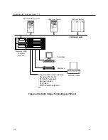
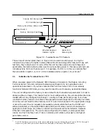
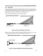
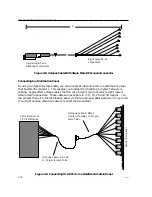
This chapter describes the cabling and signal distribution considerations for Terminal
Server 720. Some of the cabling and distribution items are available from Xyplex. Other
cabling items are supplied by the customer. Depending on your application, there are different
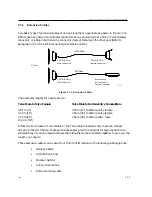
cabling schemes that you can use. Figure 3-1 provides an overview of the cabling and
distribution options available to you.
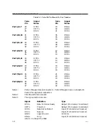
Serial connections are made at connectors on the I/O module. A signal listing is included for
each cabling option so you will be able to understand how to wire/connect to devices.
For each cabling option, pinouts are included so you will be able to wire/connect to serial
devices. Refer also to the Customer Device Wiring Considerations description in Section 3.3.2
(RJ-45) or 3.3.12 (Telco) for information regarding DTE-to-DTE and DTE-to-DCE (crossover
and straight through) connections.
0021
3-21

