

IR860
SMD/BGA Rework System
Operating Manual
„
T
hank you for choosing XYTRONIC IR Solderlight. This appliance is specially designed
for SMD/BGA rework and also very convenient for re-balling smaller BGA components.
When used in conjunction with our Infra-Red Preheater, the system will achieve
remarkable improvements in quality and efficiency of SMD/BGA rework operations.
Please read this manual carefully to maximize the advantages of using your new
SMD/BGA rework system and keep this manual readily accessible for reference.
C a t a l o g u e
●
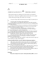
Introduction (Warning & Caution)……………………………….P. 3-4
●
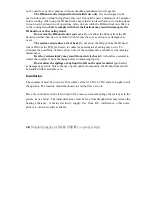
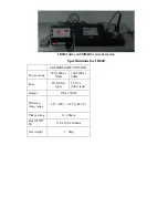
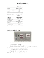
Installation and Specifications
………..……………………..
P. 5-6
●
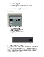
Features…….……………………………..….…….…………….P. 7-9
●
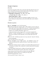
Principle of operation and Preparation.…………………….…..P.9-13
●
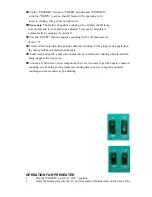
Soldering ………………………………………………………...P. 15
●
Desoldering………………………………………………………P. 15


