Revision 3.1
WebRelay
TM
Users Manual
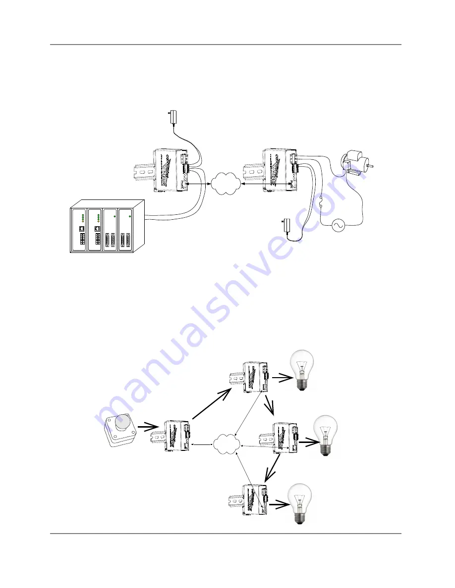
Another way this configuration is useful is to extend the output of a PLC (Programmable Logic Controller)
in a factory to control a motor in another building. The output of the PLC is connected to the input of one
WebRelay
TM
, and the motor is connected to the relay contacts of a second WebRelay
TM
. This allows any
PLC to control devices across an IP network.
1.4.4 Multiple WebRelay
TM
Operation (No Computer Required for Operation)
For some applications, it is useful to for one WebRelay
TM
to control multiple WebRelays at remote
locations. There is not a way to configure a single WebRelay
TM
to control multiple WebRelays directly, but
it is possible to set up multiple WebRelays in a daisy-chain mode so that one WebRelay
TM
controls a second
WebRelay
TM
which, in turn controls a third WebRelay
TM
and so on. In the illustration below, each
WebRelay
TM
is numbered (1, 2, 3, and 4). A mechanical switch controls WebRelay
TM
1, and
WebRelay
TM
1 controls WebRelay
TM
2, which controls WebRelay
TM
3, which controls WebRelay
TM
4. This
daisy-chain mode is set up by configuring the Relay options in WebRelays 1, 2 and 3 to “
remote command
Xytronix Research & Design, Inc.
page 9
WebRelay
11
1
Power Supply
(Powers WebRelay)
(5VDC or 9-28VDC)
+
5V
D
C
Vin
+
Vin-
In+
IP
Network
Device to be
Controlled
WebRelay
COM
NO
11
1
Power Supply
(Powers WebRelay)
(5VDC or 9-28VDC)
+
5V
D
C
Power Source
(For device to be controlled)
Fuse or
Circuit Breaker
Vin+
Vin-
Programmable Logic Controller
(PLC)
Digital Output
Gnd
RS
-232
AN1
AN2
AN3
AN4
AN5
Power
AF1
AF3
Warn
R
S-232
AN1
AN2
AN3
AN4
AN5
Di
gital I
N
Di
gital OUT
Power
Di
gital IN
Di
gital OU
T
Power
Power
AF1
AF3
Warn
In-
WebRelay 1
11
IP
Network
Control Switch
Device To Be Controlled
Device To Be Controlled
Device To Be Controlled
WebRelay 2
WebRelay 3
WebRelay 4


