28
XYZ Machine Tools
ProTURN SLX 1630 ProtoTRAK SLX CNC Safety, Installation, Service & Parts List Manual
If calibration factors are being saved, but the measurements are not repeating or are not
accurate:
See Measurements Are Not Repeating
See Measurements Are Not Accurate
3.3.11 E-Stop Error
The E-Stop turns the power off to the axis and spindle motors. The 1630 has an e-
stop on the front of the pendant and a green E-stop reset button on the side of the
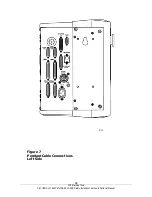
pendant. (See figures 6 & 8)
For the axis motors this is done by stopping 110V power from reaching
the cable breakout box through the use of a relay in the pendant. The
AC E-stop out connector on the pendant should not have 110 volts
coming out of it when the E-stop is pressed.
The AC drive power is turned off by a contact relay (K1), located on the
power module. The contact relay (K1) is turned off by the dual channel
relay (safety relay), which is controlled by the E-stop on the pendant.
The E-stop LED on the spindle control module will be on when the e-stop
is in the out position. The LED will turn off when the E-stop is depressed.
(See figure 11)
Once power reaches the cable breakout box it distributes power to the
axis motors, auxiliary functions. If power does not reach the cable
breakout box then none of these functions will work.
If the E-Stop button is depressed, and no message is displayed on the screen, then
either the E-Stop button, pendant, spindle control module, cables from pendant to
spindle control module, or cables from spindle control module to dual channel relay
(safety relay) is at fault.
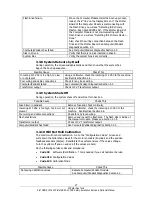
Possible Cause
Check This
E-Stop reset button
Press the E-Stop reset button on the side of the
pendant.
Faulty E-Stop switch
Check the cable connections from the computer
module to the E-Stop switch. Check the E-Stop switch
for functionality.
Bad pendant
Does 110 V power come out of the cable breakout box
power cord on the pendant? If yes and the screen
has an E-stop message then replace the pendant.
Poor cable connection
Check spindle control cable connection at the pendant
and spindle control box.
E-Stop jumper
Verify the E-Stop jumper in the electrical box on the
spindle control module is correct.
3.4 Problem with the Measurements
3.4.1 X and Z-Axis Measurements Do Not Repeat
With a dial indicator mounted to the bottom of the spindle, touch off a fixed surface
either in the X or Z-axis direction and then set the DRO equal to 0. Crank away
several inches and then touch off again at the same place. If the reading has not
returned to 0 on the DRO, zero the display and repeat the procedure. If the
measurement does not repeat, you have a repeatability problem that must be
resolved.


