Skystream Owner’s Manual
3-CMLT-1054 Rev O XCO 1191
Pg. 43
2-1-6-3 Using Exothermic Welding
Bond the grounding conductor to the tower base flange by exothermic welding of the conductor
to the base flange. Make exothermic welds strictly in accordance with the weld manufact
urer’s
written recommendations.
Electrode conductor routing and placement / installation:
Ensure that the grounding conductor has no sharp bends in it. This is important to keep its
inductance low. The grounding conductor may be buried or contained in a conduit as explained
in 2005 NEC article 250.64.
2-2 Electrodes encased in the concrete of the tower foundation
(reference 2005 NEC article 250.52(A)(3))
A grounding electrode may also be encased in the concrete of the tower foundation. The
electrode is located at the bottom of the foundation and connects to the tower mounting bolts and
to the tower base by means of a grounding conductor.
Because the grounding electrode will be encased in concrete it should be inspected and approved
prior to pouring the foundation to avoid conflicts with local construction inspectors.
Two types of electrodes, their locations and their connection to the electrode grounding conductor
are described below:
a)
The electrode must be at least 6.0 m of one or more (electrically connected by steel tie wires)
bare or zinc galvanized steel or other electrically conductive coated steel reinforcing bars or
rods of not less than 13 mm in diameter, located near the bottom of the concrete foundation
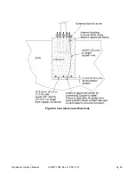
that is in direct contact with the earth. The electrode must be encased by at least 50 mm of
concrete as shown in Figure 4. The reinforcing bars, if bare, must not be rusted at the time of
installation to prevent bad electrical connection between bars and with the grounding
electrode conductor. The reinforcing bars must be electrically connected to the anchor bolts
either using the steel tie wires or using the grounding electrode conductor. The grounding
electrode conductor must not be smaller than 4 AWG copper and must be electrically bonded
to the bottom reinforcing bars using listed/approved means that is suitable for concrete
encasement. Sufficient extra length of the conductor must be available to bring it out of the
foundation top and at least 46 cm above the foundation top. It should then be bonded to the
tower as described in section 2-1-6 of this document.
b)
The electrode must be least 6.0 m of bare copper conductor not smaller than 4 AWG. The
copper conductor, which may be in the form of a coil, must lie at the bottom of the foundation
with either a 5 cm thick (maximum) tamped fill of earth covering the grounding coil or covered
in concrete a maximum of 5 cm above the soil at the bottom of the foundation. Sufficient extra
length must be present in the copper conductor to bring it at least 46 cm above the foundation
top where it should be bonded to the tower as described in section 2-1-6 of this document. On
its way up, the copper conductor must also be bonded to the tower anchor bolts using a clamp
listed or approved means that is suitable for concrete encasement and also suitable for
connecting copper to steel. This listed clamp is generally tin plated and must be of the type to
prevent direct contact between copper and steel to prevent corrosion.
2-3 Bolting Grounding Lug to Tower Base
An alternate method of attaching the electrode grounding conductor to the tower is to drill a hole
through the base and use a commercially available lug as shown in Figure 2. To connect the
grounding conductor to the tower base using this approach drill a 6 mm hole through the tower
base. After joining the grounding conductor to
the listed lug according to the lug manufacturer’s
instructions, bolt the lug to the tower base with a stainless steel bolt and self-locking nut. The
listed lug is generally tin plated and prevents corrosion between the galvanized steel tower and
the copper conductor.


