
Components and Connection Overview
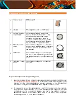
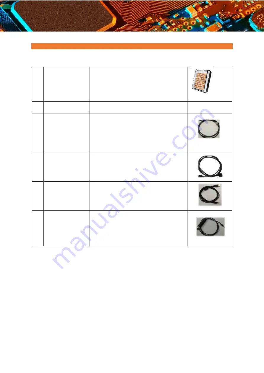
1
Scanner board
EMScannerR
2
Adapter
The adapter controls the EMScanner
3
RF SMA to type N
coaxial cable
It is referred as the RF cable in this
manual. It connects the scanner to the
spectrum analyser and has a SMA
connector for the scanner and a N
connector for the spectrum analyzer 50
ohm input port. It transmits RF output of
the scanner to the spectrum analyser.
4
Micro-D control
cable
It connects the adapter to the scanner to
enable control of the EMSCAN’s patented
scanner’s switched probes and to power
the scanner.
5
USB Cable
It connects the PC (laptop or desktop) to
the adaptor. The USB Cable provided with
the system has ferrites on both ends of the
cable
6
SMB-BNC Trigger
Cable
It connects the adaptor to the spectrum
analyser
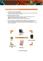
Required Components (Supplied by user)
1.
Spectrum Analyzer
: It must include the necessary options to work with the EMScanner
(
see Supported Spectrum Analysers
). It measures the radio frequency (RF) signal
received from the EMSCAN’s patented scanner, generated by the very-near-field
emissions of an adjacent activated PCB and it outputs the data to the PC.
2.
PC (Laptop / Desktop)
: It must support a LAN 10/100 connection to the spectrum
analyzer and a USB connection (version 2.0 or higher) to the adaptor or two USB
connections, one for the spectrum analyzer and one for the adaptor. It runs the
EMScanner software and receives data, which it can display and manipulate
immediately or store for future data presentation.


