background image

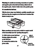
Warnning: be careful not reversing connection of  positive 

and negative pole to the bait boat battery. (black wire is 

for negative pole;  black & white wire is for positive pole)

10. assemble the bait boat.

With the above steps were finished, carefully assemble your

bait boat, then the complete set of bait boat & wireless fish

finder is ready to use.

Note: sometimes you may need a switch to control on/off 

of the RemoteEye (see the “packing list-page2”).

1). Drill a hole on your bait boat

housing, tighten the switch

on the bait boat.

2). connect the switch to the

power cable.

conect to 
power cable

hull of
bait boat

Warnning:

Warnning: be careful not reversing connection of  positive 

and negative pole to the bait boat battery. (black wire is 

for negative pole;  black & white wire is for positive pole)

10. assemble the bait boat.

10. assemble the bait boat.

With the above steps were finished, carefully assemble your

bait boat, then the complete set of bait boat & wireless fish

finder is ready to use.

Note:

Note: sometimes you may need a switch to control on/off 

of the RemoteEye (see the “packing list-page2”).

1). Drill a hole on your bait boat

housing, tighten the switch

on the bait boat.

2). connect the switch to the

power cable.

conect to 
power cable

hull of
bait boat

Warnning: be careful not reversing connection of  positive 

and negative pole to the bait boat battery. (black wire is 

for negative pole;  black & white wire is for positive pole)

10. assemble the bait boat.

With the above steps were finished, carefully assemble your

bait boat, then the complete set of bait boat & wireless fish

finder is ready to use.

Note: sometimes you may need a switch to control on/off 

of the RemoteEye (see the “packing list-page2”).

1). Drill a hole on your bait boat

housing, tighten the switch

on the bait boat.

2). connect the switch to the

power cable.

conect to 
power cable

hull of
bait boat

Summary of Contents for FC80

Page 1: ...www goyachting cn User s manual Used with bait boat Monitor bait boat battery 300m RC distance MENU MENU EXIT EXIT ENT ENT BA IT BO AT FIS HF IND ER FC 80 FC 80 FC 90 FC 90...

Page 2: ...or end our policies regulations and special offers at any time We reserve the right to change or improve its products and to make changes in the content without obligation to notify any person or org...

Page 3: ...stall the RemoteEye to bait boat 6 Introduction of RemoteEye 7 Tool list 8 RemoteEye installation method 1 8 RemoteEye installation method 2 18 Operational Panel Basic 24 Display 25 Understanding the...

Page 4: ...ID 35 Units 36 Backlight 37 Contrast 38 Load DFT 39 Monitor SEL FC90 Fishfinder only 40 BAT Alarm FC90 Fishfinder only 41 Language 42 Trouble Shooting 43 Maintenance 48 Guarantee Conditions 49 Specifi...

Page 5: ...used with bait boat We offer 12months charge free maintenance against any damages induced by non human factors and damages beyond the 12 months are handled with reasonable charges based on concrete si...

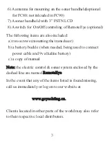
Page 6: ...the transducer to your bait boat please check the packing list below and make sure you are not missing any items 1 A wireless remote sonar sensor 2 A control box 3 A antenna for mounting on bait boat...

Page 7: ...b a battery buckle when needed being used to connect power cable and 9v alkaline battery c a copy of manual Note Note the electric control sonar system enclosed by the dashed line are named RemoteEye...

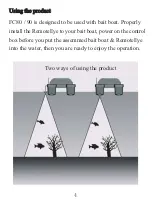
Page 8: ...s designed to be used with bait boat Properly install the RemoteEye to your bait boat power on the control box before you put the assemmed bait boat RemoteEye into the water then you are ready to enjo...

Page 9: ...batteries are aligned as per the diagram within the battery compartment 3 Slide the battery cover towards the top of the unit until it is completely closed Then turn the screw clockwise To take off th...

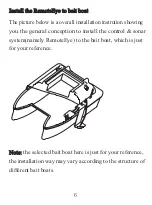
Page 10: ...tallation instrution showing you the general conception to install the control sonar system namely RemoteEye to the bait boat which is just for your reference Note Note the selected bait boat here is...

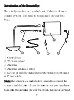
Page 11: ...to be mounted on your bait boat 1 Control box 2 Wireless sensor 3 Antenna 4 Antenna extended cable 5 Switch of on off controlling for RemoteEye optional 6 Power cable Note Note the antenna extended ca...

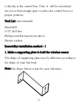
Page 12: ...32 drill bits Phillips and flat head screwdriver Marine sealant Remo RemoteEye insta teEye installation method 1 llation method 1 1 M 1 Make a supporting pla ake a supporting plate to hold the wireles...

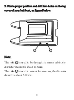
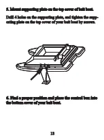
Page 13: ...and drill two holes on the top cover of your bait boat as figured below cover of your bait boat as figured below Note Note The hole is used to be through the sensor cable the diameter should be about...

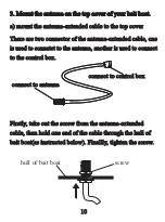
Page 14: ...e are two connector of the antenna extended cable one is used to connetct to the antenna another is used to connect to the control box Firstly take out the screw from the antenna extended cable then h...

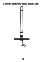
Page 15: ...b screw the antenna to the antenna extended cable b screw the antenna to the antenna extended cable b screw the antenna to the antenna extended cable...

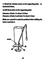
Page 16: ...ting plate as instructed below a drill three holes on the supporting plate Diameter of hole 1 is about 12 5mm Diameter of hole 2 and hole 3 is about 3 5mm Note Note use a pencil to mark the position b...

Page 17: ...boat Drill 4 holes on the supporting plate and tighten the supp orting plate on the top cover of your bait boat by screws 6 Find a proper position and place the control box into 6 Find a proper posit...

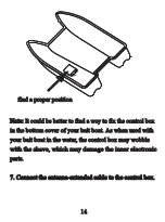
Page 18: ...of your bait boat As when used with your bait boat in the water the control box may wobble with the shave which may damage the inner electronic parts 7 Connect the antenna extended cable to the contr...

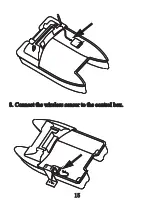
Page 19: ...8 Connect the wireless sensor to the control box 8 Connect the wireless sensor to the control box 8 Connect the wireless sensor to the control box 8 Connect the wireless sensor to the control box...

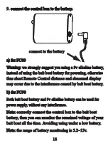
Page 20: ...ance and abnormal display may occur due to the interference caused by bait boat battery b for FC90 b for FC90 Both bait boat battery and 9v alkaline battery can be used for power supply without any in...

Page 21: ...the bait boat With the above steps were finished carefully assemble your bait boat then the complete set of bait boat wireless fish finder is ready to use Note Note sometimes you may need a switch to...

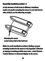
Page 22: ...he sensor to your bait boat in other method see the following example Note Note for such installation method finding a proper mounting location for the sensor is very important Otherwise an unproper m...

Page 23: ...in the area A and area B there should be no any obstacle otherwise the sonar signals will be blocked thus sonar unit will not be able to receive the signal normally which will cause short Remote Cont...

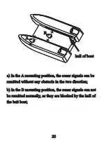
Page 24: ...ition the sonar signals can be remitted without any obstacle in the two direction b In the B mounting position the sonar signals can not be remitted normally as they are blocked by the hull of the bai...

Page 25: ...drill 3 holes on 1 Find a proper mounting position and drill 3 holes on the bottom of your bait boat the bottom of your bait boat Note Note the 3 holes should be drilled with the following dimension...

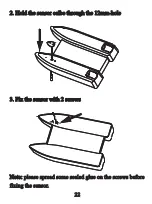
Page 26: ...r calbe through the 12mm hole 2 Hold the sensor calbe through the 12mm hole 3 Fix the sensor with 2 screws 3 Fix the sensor with 2 screws Note Note please spread some sealed glue on the screws before...

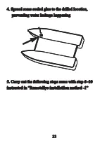
Page 27: ...drilled location preventing water leakage happening preventing water leakage happening 5 Carry out the following steps same with step 6 10 5 Carry out the following steps same with step 6 10 instructe...

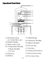
Page 28: ...lug 2 Depth Reading 3 Water surface line 4 Temperature Reading Voltage Reading 5 Fish Icon 6 Bottom 7 Depth Range 8 Sensitivity Reading 9 Battery Strength 10 Power Key 11 Ent Key 12 Menu and Exit Key...

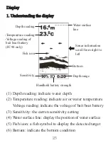
Page 29: ...vity Water surface line 1 Depth reading indicate water depth 2 Temperature reading indicate air or water temperature Voltage reading indicate the voltage of bait boat battery 3 Sensitivity the curren...

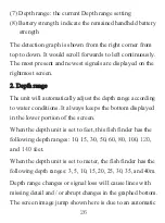
Page 30: ...ll automatically adjust the depth range according to water conditions It always keeps the bottom displayed in the lower portion of the screen When the depth unit is set to feet this fish finder has th...

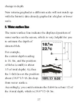
Page 31: ...the displayed position of water surface on the screen which is very helpful for you to estimate the depth of detected fish For example the current depth reading is 18 m and the position of fish a ico...

Page 32: ...nditions vary greatly so some experience is needed to get the most benefits of FC80 90 Use the message displayed in the screen as a helpful tools for your judgment thus you could exert the full functi...

Page 33: ...nction setting by simple operation 1 Power key Power on Power off Note Note to shut off the unit press the Power key and keep it for 3s then release it 2 Ent key To confirm a setting hold the screen N...

Page 34: ...ge the setting and the frame line of current menu will look thicker then non setting see following To exit the setting condition press ENT key again 3 MENU EXIT key to enter or exit menu setting 4 Up...

Page 35: ...sitivity is the more relatively strong sonar returns the screen will display If the sensitivity is decreased too low most sonar returns which maybe fish will not be displayed In situation while water...

Page 36: ...rm the setting 6 Press EXIT to exit Channel Channel Channel make it possible for you to switch using between the wireless model and another wire model NAKI8850B provided that you have bought one CH1 C...

Page 37: ...e alarm s setting You also could exit alarm mode by enter into Shallow menu and artificially increase the current depth alarm value to a safe grade To set the Shallow 1 Press MENU to enter into menu s...

Page 38: ...and the current Depth Range is 20m then the bottom will display on 50 portion of the screen To set the Depth Range 1 Press MENU to enter into menu setting 2 Use the Up Down Arrow to select Depth Rang...

Page 39: ...between fish and other suspended objects such as turtles trotlines submerged floats air bubbles etc One word it could be fooled So you may see fish icon on the screen actually there is no fish underwa...

Page 40: ...p Down Arrow to select Fish ID option 3 Press ENT to confirm selecting 4 Use the Up Down Arrow to change the value 5 Press ENT to confirm the setting 6 Press EXIT to exit Units Units Units is used to...

Page 41: ...e Up Down Arrow to change the value 5 Press ENT to confirm the setting 6 Press EXIT to exit Back Backligh light Backlight is used to let you choose whether the backlight is on or auto in some envirome...

Page 42: ...to let you get a most suitable display when you operate the unit To set the Contra Contrast st 1 Press MENU to enter into menu setting 2 Use the Up Down Arrow to select Contrast Contrast option 3 Pres...

Page 43: ...ttings To set the Load Load DFT DFT 1 Press MENU to enter into menu setting 2 Use the Up Down Arrow to select Load DFT Load DFT option 3 Press ENT to confirm selecting 4 Use the Up Down Arrow to chang...

Page 44: ...rature Battery Air Temp Water Temp To set the Monitor SEL Monitor SEL 1 Press MENU to enter into menu setting 2 Use the Up Down Arrow to select Monitor SEL option 3 Press ENT to confirm selecting 4 Us...

Page 45: ...tone appears run your bait boat back as soon as possible You also could exit alarm mode by enter into BAT Alarm menu and artificially increase the setting to a safe value To set the BAT Alarm 1 Press...

Page 46: ...n English German French Russian To set the Language 1 Press MENU to enter into menu setting 2 Use the Up Down Arrow to select Language option 3 Press ENT to confirm selecting 4 Use the Up Down Arrow t...

Page 47: ...e Company are entitled to any repair necessary We have been contacted frequently by our customers req uesting repair service We inspect their products and find many of them are not in need of repair t...

Page 48: ...in water again and signals are restored 1 FC80 90 is a product depending upon line of sight Obstacles between the handheld and the sensor can con tribute to signal loss 2 FC80 90 has a detection dept...

Page 49: ...eas the screen does not display things normally and depths are not does not display things normally and depths are not indicated with consistency indicated with consistency The sensor has a perfect pe...

Page 50: ...r a Oil dirt and fuel might cause a film to form on the sensor and reduce its effectiveness Cleaning the surface of the transducer might help b Electrical noise nearby can interfere with the sonar whi...

Page 51: ...location will cause abnormal display b Please check whether you are using the bait boat batt ery for power suppling For FC80 we strongly suggest you connecting the RemoteEye to a separate 9v Alkaline...

Page 52: ...screen with a cloth dipped mild detergent solution and then wipes it dry 2 F 2 For the screen or the screen Use a piece of soft cloth or pelt to clean the screen fresh water or eyeglass cleaner can be...

Page 53: ...cts exceeding the warranty coverage the maintenance department will charge customers some fees according to the real situation 2 This warranty is void if damage or malfunction is due to abuse misuse a...

Page 54: ...klight On Auto Visible under strong sunlight 2 Sonar Radio Depth Capability 1 0 30m Wireless Operating Range Max300m Sonar Frequency 115KHZ Sonar Beam Angle 80deg 10db Radio Frequency 433 9 MHz Sonar...

Page 55: ...urs Continuous Use Handheld Power Off Automatically In 10minutes Without Any Using RemoteEye Power Supply 6 12v battery 2 Features 2 Features 1 Switchable Fish Identification Mode 2 Sensitivity 0 100...

Page 56: ...days By telephone Monday Friday 8 am to 5 30 pm Central Standard Time 0086 25 84680809 Or by e mail Typically we respond to you in 2 business days info goyachting cn For direct shipping our address is...

Page 57: ...Scale 1 1 Unit mm...

Page 58: ...www goyachting cn...

Reviews: