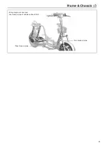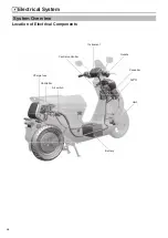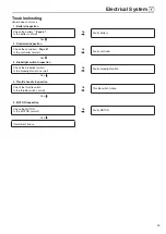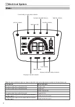
Frame & Chassis
40
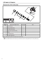
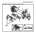
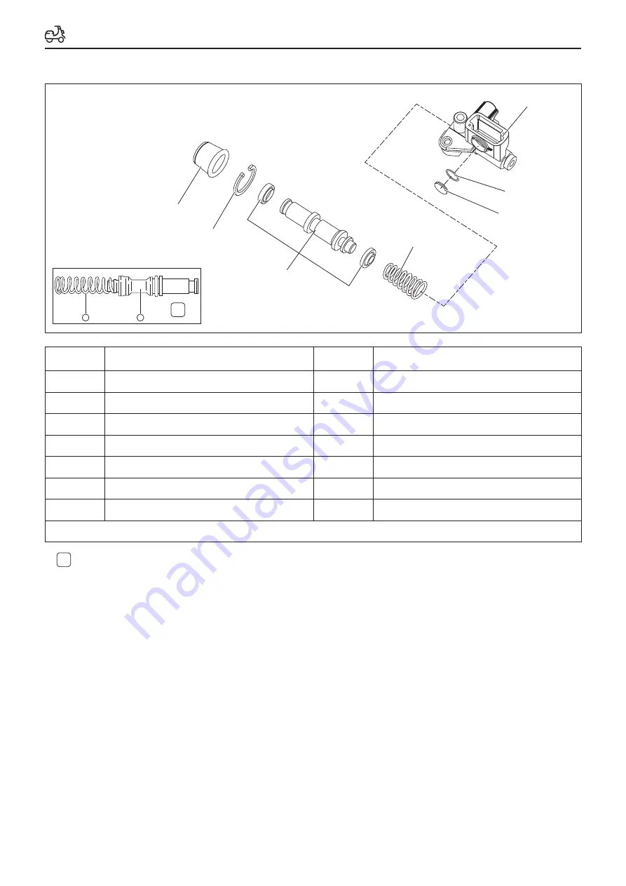
Disassembly of the brake pump
1
6
7
5
4
3
2
1
2
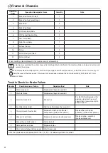
Operation
Order
Operation Name/parts Name
Quantity
Note
1
Main Pump Body
1
2
Dust-proof Robber Ring
1
3
E-shaped Retaining Ring
2
4
Main Pump Thruster Components
1
5
Spring
1
6
Oil Level Sight Glass
1
7
O-shaped Rubber Ring
1
When installing, please proceed in the reverse order of disassembly.
When installing the brake master cylinder, the small diameter end of the spring should face the master cylinder piston.
Summary of Contents for C1S
Page 2: ......
Page 14: ...General Information 12 Rear brake oil pipe Motor line Motor line Motor line...
Page 48: ...MEMO...
Page 77: ...Electrical System 75 GPS Front Wall Page 21...
Page 87: ......
Page 88: ...2020 06 29 The first revision...

