


5
Alignment
Introduction and Precautions
The following procedures cover adjustments that are
not normally required once the transceiver has left the fac-
tory. However, if damage occurs and some parts subse-
quently are replaced, realignment may be required. If a
sudden problem occurs during normal operation, it is like-
ly due to component failure; realignment should not be
done until after the faulty component has been replaced.
We recommend that servicing be performed by autho-
rized Yaesu service technicians, who are experienced with
the circuitry and fully equipped for repair and alignment.
If a fault is suspected, contact the selling dealer for in-
structions regarding repair. Authorized Yaesu service
technicians have the latest modification information, and
realign all circuits and make compete performance checks
to ensure compliance with the factory specifications after
repairs.
Those who do undertake any of the following align-
ments are cautioned to proceed at their own risk. Prob-
lems caused by unauthorized attempts at realignment are
not covered by the warranty policy. Also, Yaesu must re-
serve the right to change circuits and alignment proce-
dures, in the interest of improved performance, without
notifying owners. Under no circumstances should any
alignment be attempted unless the normal function and
operation of the transceiver are clearly understood, the
cause of the malfunction has been clearly pinpointed and
any faulty components replaced, and the need for realign-
ment determined to be absolutely necessary.
The following test equipment (and thorough familiari-
ty with its correct use) is necessary for complete realign-
ment. Correction of problems caused by misalignment
resulting from unauthorized adjustments made with im-
proper test equipment is not covered by warranty. Al-
though most steps do not require all of the equipment list-
ed, the interaction of some adjustments may require that
more complex adjustments be performed afterwards. Do
not attempt to perform only a single step unless it is clear-
ly isolated electrically from all other steps. Rather, have
all test equipment ready before beginning, and follow all
of the steps in a section in the order they are presented.
Required Test Equipment
m
Digital DC Voltmeter (high-Z, 1 M
W
/V)
m
DC Ammeter
m
AC Voltmeter
m
RF Standard Signal Generator w/ calibrated output and
dB scale, 0 dBµ = 0.5 µV
m
AF Signal Generator with calibrated output
m
Frequency Counter
m
50-
W
Dummy Load (150 ~ 250 watts)
m
50-
W
Resistor, 1 Watt (low-power dummy load for cir-
cuit termination)
m
16.6-
W
Dummy Load (150 watts)
m
In-Line Wattmeter (150 ~ 250 watts, 50-
W
)
m
Linear Detector
m
RF Attenuator (150 watts, 50 dB) or sampling coupler
m
Spectrum Analyzer good to at least 1 GHz
m
SINAD Meter
Alignment Preparation & Precautions
A 50-
W
dummy load and in-line wattmeter must be con-
nected to the antenna jack in all procedures that call for
transmission, except where specified otherwise. Correct
alignment is not possible with an antenna. Except where
specified otherwise, the transceiver should be tuned to
14.2000 MHz, USB mode, and these controls set as indi-
cated:
m
AF
fully CCW
m
SQL/RF
fully CCW
The transceiver’s Alignment Routine is required for
some procedures. If an Alignment Routine cannot be se-
lected, power may have to be switched off then back on to
re-enable menu selection.
To begin, turn the transceiver off. Press the
A
,
B
, and
C
keys together while turning the transceiver on again, then
press and hold the
FUNC
key.
In the alignment procedure, each alignment parameter
is selected by rotating the main
D
IAL
. To exit the align-
ment routine, press the
FUNC
key. After performing the
system alignment in its entirety, individual settings can
be returned to and adjusted should the need arise.
Read each step to determine if the same test equipment
used in the previous step will be required. If not, remove
the test equipment (except dummy load and wattmeter, if
connected) before proceeding. Correct alignment requires
that the ambient temperature be the same as that of the
transceiver and test equipment, and that this temperature
be held constant within 68 ~ 86°F (20 ~ 30°C). If the trans-
ceiver is brought into the shop from hot or cold air, it
should be allowed time for thermal equalization with the
environment before alignment. Alignments must only be
made with oscillator shields and circuit boards firmly af-
fixed in place. Also, the test equipment must be thoroughly
warmed up before beginning.
Notes: Signal levels in dB referred to in alignment are based on
0 dBµ = 0.5 µV (closed circuit).
Table Note: DC voltages should be within ±10 % of those listed
in the voltage tables.
Summary of Contents for FT-100 Micro Mobile
Page 12: ...12 Alignment Note ...
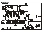
Page 17: ...17 Block Diagram ...
Page 18: ...18 Interconnection Diagram ...
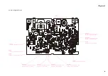
Page 19: ...19 Circuit Diagram MAIN Unit Lot 1 4 ...
Page 20: ...20 MAIN Unit Lot 1 4 Note ...
Page 23: ...23 MAIN Unit Lot 5 Circuit Diagram ...
Page 24: ...24 MAIN Unit Lot 5 Note ...
Page 51: ...51 Circuit Diagram Parts Layout Side A Side B DAN235U M D1801 1802 1803 1804 BPF Unit ...
Page 52: ...52 BPF Unit Lot 9 Circuit Diagram Parts Layout Side A Side B DAN235U M D1801 1802 1803 1804 ...
Page 54: ...54 BPF Unit Note ...
Page 55: ...55 Circuit Diagram Parts Layout Side A Side B 2SC4047 ZY Q1901 1902 HPF Unit ...
Page 56: ...56 HPF Unit Lot 6 Circuit Diagram Parts Layout Side A Side B DTC114EU 24 Q1901 1902 1903 ...
Page 58: ...58 HPF Unit Note ...
Page 59: ...59 Circuit Diagram Parts Layout NJM2904V Q1951 1952 Audio Filter Unit Side A Side B ...
Page 60: ...60 Audio Filter Lot 6 Circuit Diagram Parts Layout Side A Side B NJM2904V Q1951 1952 ...
Page 62: ...62 Audio Filter Unit Note ...
Page 63: ...63 Local Unit Circuit Diagram ...
Page 74: ...74 Local Unit Note ...
Page 75: ...75 REF Unit Circuit Diagram Parts Layout Side A Side B 2SC2714Y QY Q2801 2802 ...
Page 77: ...77 PA Unit Circuit Diagram ...
Page 78: ...78 PA Unit Note ...
Page 88: ...88 PA Unit Note ...
Page 89: ...89 Circuit Diagram LPF Unit ...
Page 91: ...91 Circuit Diagram LPF Unit Lot 9 ...
Page 98: ...98 LPF Unit Note ...
Page 99: ...99 Circuit Diagram Display Unit Lot 1 ...
Page 101: ...101 Circuit Diagram Display Unit Lot 34 ...
Page 106: ...106 Display Unit Note ...
Page 107: ...107 Circuit Diagram CNTL Unit Lot 1 3 ...
Page 109: ...109 CNTL Unit Lot 4 Circuit Diagram ...
Page 116: ...116 CNTL Unit Note ...


