background image

Summary of Contents for FT-180A

Page 1: ...FT 18 a INSTRUCTION MANUAT YAESU INUSEN CO I TD cPo Box 1500 TOKYO JAPAN ...

Page 2: ...PECTFICATIONS SEMICONDUCTORS FRONTPANIL CONTROLS AND SWTCHES REARPANELCONNECTIONS INSTALLATIONS 7 oPERATION 13 CIRCUIT DESCRIPTION 16 MAINTENANCEAJ D ALIGNMENT 28 MODIFICATIONS 36 PARTS LIST 45 l I 2 3 4 5 I o tr v t t4t 4 ...

Page 3: ...onceinstallationiscompleted no further tuning prccedureis r quiredfor full opemtionon eachchannel The Fi_180A is paokaged in a heavy gaugemetarcasefor excellentmechanicar stability and the final amplifierttansistors arefully protectedagainst possible damage from highantenna Swn Optional accesso ios include the FC 420RemoteControlledAntennaCoupler FH_lgO RemoteController with telephone type handset...

Page 4: ...band supptession Betterthan50 dB Carriersuppression Betterthan50 dB Spudousemissionsi Betterthan 65 dBdown Third orderdistortionproducts Betterthan3l dB down Transmitter frequency rc6ponse 300 2700Hz 6 dB Maximumbandwidth 3 kHz SSB Srability Betterthan110 ppm Distortionptoducts 20 dB or better Microphone impedancei 600 ohms dynamic Tone signal 1500Hz Antennaoutput impedrncei 50 ohmsnominal RXCEIVE...

Page 5: ...C2395 2 i HZ3CI Zener 2 i 2SKI92AGR 3 2SC24O 7 2 2 l 2SKl25 4 25C2509 2 FC63 Varactor I 3SK73GR 9 2SD288K l1 2SD71 O 2 t l00Wmodel Transistorsi 2SD844K I t 50Wnodel 2SA564Q 2 lOWmodel 2SA564R I Diodes withcrystal oven 2SC496Y lN2 0 l7 ACCESSORTES Micrcphone YM 36 1 M3090026 DCPower Cord I lOWmodel T9006806 50wmodel T9006815 100W model T9006820 Miniature Extemal Speaker Plug P2240 I P0090034 Headph...

Page 6: ...LL This is a momentaryswitchusedfor sendingtone callingsignals as well asfor calibnting the trans ceiverfor incomingsignals 6 METER This switch selectsthe display function for the fiont panelmeter On rcceive thismeterfunctions asa signalstrengthmeter S meter On transmit thesource voltage final amplifiercollectorcurrcnt rclativepower output or reflectedpower can be displayed 7 MODE Thisswitchselect...

Page 7: ... j0ck accepts the antenna cable 4 POWER Conn ctthe DC power cord at this point Nevel apply AC pover or improper DC input voltages to this tnnsceiver 5 REMOTE This blue 20 pinconnectoraccepts thepowerand control signals from the optional FH 180 Remote Controller which providesremotecontrol of the CHANNEL selector AF GAIN and CLAR func tions as well as microphoneinput and audio output from a telepho...

Page 8: ...36 VIEWEDFROM A SIOE MICROPHONECONNECTIONS HEADPHONE CONNECTIONS MICROPHONEPLUG EXTERNAL SPEAKER CONNECTIONS a b IOOIY Ttp 2OA 50W Ttp l5A IOW Tt 6A DCPOWER CORDCONNECT I SATTEBY OR IOCSUPPLY _ J TEFMLNAL IONS 6 ...

Page 9: ...uldbe installedon both endsof the antenna irnd a suitablecenterinsulatormust irlso be Lrsed llowever sometypesof antennabaluns inclLrde mountinghooksfor thc antenna elements thus eliminatingthe need for a centerinsulator These parts may be obtainedfrom your Yaesu dealer The correctlengthfof a doubletor dipole antennacan be determjnedbl usiig one of the followingfonnulasl Cut the appmpdatelengthof ...

Page 10: ...xtending radiallyfrom the centorol theaDtenna lnd bu cd slightlybeneaththe suifaceof the ground A cold water pipe may providea usablegroundin many instances On yachts the ground lbil in the hull must be used The vertical radiator must be insulatedfrom grcund and it should not touoh anytrces buildings or rigging onyachts For all antennatypes becertainthat the FT l80A meter needle when switchedto th...

Page 11: ...use 10watt model 6 ampere fuse Connect the RED power supply lead to the POSITIVEsupply post and connectthe BLACK powersupplyleadto theNEGATIVEsupplypost The DCcordis includedwith the transceiver AC OPERATION The FP 700will allow opemtion from AC supply voltases of 100 1 10 1 17l20Ol22O1234 wlts 50160 Hz Beforecommencing operationwith theFP 700 be absolutelycertainthat the voltag specification mark...

Page 12: ... lt l 1 L n ttT ilffif 1i H k I io o E 1 i _1e I L _ AY_E J l_P e_ 1 _ _ J t Eirq l 7 lro roo o 1T to too o f r I r f r fF l rrfFIr Ir ll 1l l1 Fll ll 1ll rtrll I tr II II II If l 7V POWERTRANSFORMERPRIMARY CONNECTIONS AC to0v AC 34V AC 2 AV 200v tov l lii tr D 7 t A CIRCUIT DIAGRAM IO ...

Page 13: ...se producing circuit The powerleadsmust be kept asshortaspossible and shouldbe kept away lrom iglition cablesas muchaspossible When making battery connections be certainto connect the RED power cablel adto the POSI TIVE battery terminal and the BLACK lead to the NEGATIVE terninal Befoferonnecting theDC cxble o thelransceiver checkthebrlteryvoltage wilh theengine running fast enough to show a charg...

Page 14: ...themounting holes Usea 3 16 diameter bit for drillingthese holes allowingenough room for the trans ceivei its cables microphone and controls Secure themounting bracket withthescrews washers and nutssupplied asshownin the dmwing 3 Usingthe slottedknob screws attachthe FT 180A to theMMB 2 universal bracket 4 The angle of thetransceiver maybeadjusted to whatever positionis mostconvenient and easily a...

Page 15: ...eincoming signal turn the NB switch ON Most pulse type noiseswill be eliminated by theblanker although some atmospheric and man made white noisewill not be totally removed 10 To transmit pressthe microphonepush to talk switch and speakwith a nomal voice into the microphone Release the switchfor rccerver recovery SELECTIVECALLING FEATURE A 1500Hz tone generator is available for selective calling Ca...

Page 16: ...W 4 ohms Handset Microphone 68 dBmoutput 600ohms Dimensions WHD 80x 120x 240mm Weight l 4 ks Installation The FH 180canbeinstalledin anydesired mounf ingposition andon anysudace 1 The suppliedmountingbrackets canbe posi tionedso that the mountingscrews areeither undertheController or on eitherside accord ing to individualrequirements lf the mount ing scrcwsarc to be locatedunderneaththe Controller...

Page 17: ...handset To disable the FH 180 speaker set the SPEAKERswitchto the MUTE position This will silenoethe FH 180 speakerwhen the handsetis removedfrom the cradle though the speakerwill be reactivatedwhen thehands t isreplaced To transmit when usingthe FH 180 squeeze the PTT switch on the inside centet ol the handset handle and talk Releasethis switch to rctum to rcceive The CALL and CLAR controls on th...

Page 18: ...for the noise blanker circuit The signalthen passes through noiseblankerdiodesD1o 6Drors which act as switchesddvcn by noiseblankercontrollerQ2o s 2SCl8l5GR The IF signal is arrplified by Q n65 2SK192ACR and then deliveredto a crystal filter for USII LSB or AM whcrc Luwanted adjacentsignalsare cut out Finaily the lti signdl fron thecrystalIilter is fedtluoughdiodeswitches to a three stage lF ampli...

Page 19: ... signalfrom microphone jack Jor is fed to J3oo on the AF unit Thespeech signal is amplified by Q3oo 2SC732BL lnal delivereal through microphonegain control potentiometer VR3 r to two stagesof AF amplifief e3oo 2SC 32GR andetrooa 2SCl8l5y Theoutput from the emitter of Q oo is applieclto clouble balanced modulatorQrooe MCl495p wherethe amplifiedspeechsignaland appljedcardersignal producea DSB signal...

Page 20: ...signal is thendolivered to theLPFunit ALC Circuit A varietyof levelcontrolsystems argincluded in the FT 180Afor protectionagainst overdrive and hish SwR At the dirctional coupler the output voltage is sensed and wher a high SWR condition existg the voltageis detectedby D on D o1r tSS97 and the overd iveAl C voltageis detectedby D orr D or lSS97 Thcaercctified ALC control voltages arg amplified tog...

Page 21: ... H sFt r 3 gr R 4e _ liisfl 1 T _ f I I I il Lef I l 83 l T trl ma i bi l lIFF l I F T _ i l arir8l ratsl qsili illt l Sl i E leli firrt i ltiltf l 1 i 1 lrIsl t8F t i J l ii r r1EfiEl itEl tl tr l 15 l i r 13 lli L F ffi t ri l I I l i I a l 1 _ sli i r i I r _ r lc5 l j ti iL J rl i ri t i I rrE l l i _I LI I l iif I El li r l iEl ir Es L i ls ...

Page 22: ...ll _l NZ g Is i i I z a r l l t li3 3t fi I J 3 20 ...

Page 23: ... s 9Il 5i c E3 6 l l l i ii sl gti egrfrnFr i s3 I 6t 19 qR 6i al I tt R 6 ri 8 fl i a i s5 i t I i g 3 z ii Ei itb l 6 i 1 Ht E 6 2A S9 ...

Page 24: ...5 F i i g i E E ES E 93 E R P5 sj is EY g 22 tr ...

Page 25: ...Lo _9 eH lqs oo3ogr t E 69 i l I REG CoNTRoL UNIT PB 2271E lNo soxx ...

Page 26: ... r ii iiis Bg 6 3g 6fi i T i t t 4Pl r q t i 1ld i trLi i H I i L 24 ...

Page 27: ...l iJ i aI 6 n t c_ F I I I I I I I I I I I I I I I I I I I I I I i il I d 6 gi 3 E i dd K ff s grt 3 _l 3 l B BH 6 6q fl 5 3 t 25 ...

Page 28: ...ow AMPUNfr Pg 2t499 4ota t2 J I ot 2SC2r66 a o3 2SC2509 IOWPA UNIT 5ow loowPAUNIT if ltti 1 j t tt 3 I EE e ri niffe rqrHl 1 rs r Fr E T c33 c35 T03 LO020632 LAO212a4 i3s l e 32SC2509 ltr Elildi siiTBA 26 ...

Page 29: ... utu i l REI1OTECONTROL UNIT Pe 24 3 NO 15 i t L__ DI AGRAI 1 I I I I ii r i l l ...

Page 30: ...iailure rlrlherthan misalignmenl Sc icc must be peffollnedonly by expericnced pcfsonnel Lrsing thcproper testequipment n CARRIER LOCAL UNIT AND ALIGNMENT EQUIPMENTREQUIRED 1 RF SifnalGenerator Hewlett paokard Model 606A or equivalent with onevolt output at 50 ohms andfrcquencycoverage to 30 MHz f VacuumTubeVoltmeter VTVM Hewlett Packard Model410B or cquivalent with an RF probe goodto 40 MHz 3 Dunr...

Page 31: ... 0 dB I V At 50 ohfts this ievcliscquivalent tr 107dBnr RECEIVER ALIGNMENT 1 Antenna Coil RI Coit Atignmerlt a Set the CIIANNEL selectorto thc cnannet to be aligned and thc RF GAIN control firlty clockwise b Connect the signal gener ltor to thc anrenna jlck and tune its output to the onanrlel frequency Now setthe output lcvelto 90 clll c Adjust the coils shown below for traxrmum deflection on flre...

Page 32: ...dapplya 100dB signal at 10 7MHz Adjust Troo md T o 4 a few times for minimum indicationon the audio voltmeter and meter IF Coil Adjustment Set the CHANNEL selectorto any installed channel and rotate the RF CAIN control fully clockwjse Apply an 80 dB si al from the signal generator to the ANT jaok Adjustthefollow ing coilson the IF unit for a maximumrcad ing on the S meter T o T oor Thesecoil shoul...

Page 33: ...y signatto theANT jack and with the RF GAIN control fully clock wise adjust VRroo to the point whererne S meter just startsto deflect Apply a90 dBsignalfiom thesignal generator to the ANT jack and adjust VR ooafor a deflection of 59 60dB Reducethe amplitudeof the signalgenerator to l0 dB and adjust VR oo to the point wherethe S meterjust startsto deflect RepeatStepsb and c until the properdeflec t...

Page 34: ...edto thechanneL fiequency closethe PTTswitchon the micro phone Now adjust VRroo for rtlinrmum sign3l indjcation on rheextemal receiver a rI 3 TX MixerCoilAlignment Set the CHANNEL selectorto any installed channel and disconnectPo3 from its jack J oo3 on the RF unit Connectthe RF probe of theVTVM to Jroo3 Now adjust Trors on the RF unit for a maximumreading on the VTVM TX IF Tmp Coil AliSnment Note...

Page 35: ...he S FWD metcr ALC Alignment Note Do not switch channelsor modcs duringtransmission Presetthe potentiometers andMODEswitch asfollows VRr AF Unit Full counterrlockwise VR oo IF Unit Fully clockwise VRo LPFUnit Fullyclockwise VRroo I PFUnit Fullycounterclockwise vR uo LPFUnit Full counlerclocku ise MODEswitch A3h On any channel closethe PTT switch and adjustVR oorfor a poweroutputof 50 watts on the ...

Page 36: ...ds m parallel so as to present a 17 ohm load to the amplifier l 3 SWR with rcference to 50 ohms Tum the CALIB CALL switch to CALL and adjust VRaoorfor 75 watts power output asindicatedon the wattmeter 50WPA 37 5watts 10WPA 5watts Note for 50WModel Never attempt to adjust VRroor or VRaoo3 without performingtheentireALC alignment procedurc as this may cause the final transisto to exceed the specifie...

Page 37: ...y10 700MHz Next rcmove the counter from p6oraand connectthe frequencycounter to J1qq5 on theRF unit The local oscillator frequency must be rJjustedb the appropriare lrimmercrpdii tor corrcsponding to theCHANNELselector Adjust the trimmer capacitonon the CAR RIER LOCALOSCUnit asshown below ro theexactcrystalfrcquencies CHI I TC6oo CH2 TCoon CH3r TC6oo CH4 TCun CH5 Tce os CH6 TC u ToneOscillatorAlig...

Page 38: ...he LSB Filter on the IF unit usingthe nuts provialed in the space beside the existing IF filte Solderthe pins of the filter to the circuitboard lnstall the IF Unit in exactly the same conflgumtion as beforc and securcit with the mounting scrcws Connectall plugsto theirjacks a d closethe tmnscerver MODIFICATIONS XF IO 7HL A XF 10 7 HU a FILTER 10 7 HA BOTTOM VIEW i I l l 1 1 1 I rruur I LSB FILTER ...

Page 39: ...nd so new crystalsmusr oe installed when the oven is added Seethe procedure on thefollowingpage s Unscrcw the four CARRIER LOCAL OSC Unit mountingscrews markedA on Figure2 Then rcmove the CARRIER LOCAL OSC Unit mountingplatefrom theunit Affrx the mountingplateto the crystaloven with thescrews removed step3 Securethe crystal oven with the mounting plate in exactly the sameconfigumtionas Ihe CARRIER...

Page 40: ...as two transformers together with their associatedcapacitoA whichmustbeselected to correspond with the desiredchannelfrcquency Obtainthecorect valuesfor thesettansfomersand capacitors from the BAND TABLE on page44 and installin the correctlocationson theRF Unit 2 3 1 CH6simplex orCH3TX only CHssimpl x or CH2TX only CH4simplex or CHl TX only Those locations us d orTX crystals for s mi duPlex channo...

Page 41: ...onsT oo andT1ooj and the capaoi torsin locations Croz1 andC1os3 for CH 1 Pa A in Figures7 and 8 illustratesthe jumper wiresthatmustbe connected between Jo7andJrr or Jn on the RF Unit if all six channels areto be simplex f somechannels are to be semi duplex install only those jumpers corespondingto the simple chan nel s lF SELECT SELECT iJ I T iF Figure6 39 Figure5 RF Unit l Etrnl cHl cH2 CH3 CH4 C...

Page 42: ... sameLPF bimd simply makemultiple con nections to the point adjacent to Joe NOTE Improper jumper colmectionsmay damage thelowpass filte andfinaltransistors Whenall desiredchannels havebeeninstalled rctum the RF Unit to its odginalpositionand rcplace th mountingscrcws andconnectoF u3 2m P vl ll cHl cH3 cH5 Figur 7 Chan ersl 3 and4 6 jumoered LPFFFEOUENCY FANGE 1 6rvlBz 2 6 Hz B c o E l1 1 MHz 18 0M...

Page 43: ...ectorJumper s fronl point adjacentto Jo to thepoint adjacent to J 1 for the semi duplex channel s being installed asshownin Figure9 Referringto step 5 and Part B of Figures7 and 8 in the Simplex Channelprocedure installthe LPF jump r s for theTRANSMIT frequencyin the CHl CH2 or CH3positions pointsin commonwith pins 4 5 and 6 of Jro respectively Do not installany LPF jumper for semi duplex channels...

Page 44: ...HEFH 18O 5 J1605 P47 J1601 P43 J1603 P45 Co lect one end of each of the supplied connectioncablesto the RF Unit Plo to J 6 6 P1 to J161 andP to J o Referring to Figure12 install the Remote ControlUnit suppliedwith the kit usingthe the suppliedmountingscrews Makesurethat no wiresor connectors arepinchedor trapped beneath the Unit Connectthe otherendsof thenewconnection cablesto the Remote Control U...

Page 45: ...CHANNELSWITCH Jt01lP45 J702 P46 REMOTE CNTLUNIT REMOTECONTROLUNIT TOPVIEW Fig 12 43 ...

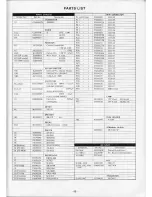
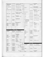
Page 46: ...021 5151 2 3 2s 3 sMHz 50wv l20prCHG02l7s12l 2 D3000120 3 5 4 5MIIx 1 00209 74 2 3 5 4 0MHz 50wV100pF CH K02175101 2 4 0 4 5MHr 50wv 75pfCH K021 9018 2 D3000121 4 5 5 0 MHz L00209 74 2 50WV 55pF CH K02175s50 D3000122 5 0 6 0MHz t 0020975 2 s 0 5 5 MHz 50wV 62pF CH K021790I 2 5 5 5 0 4Hz 50WV a pFCH k0217s470 2 D3000123 6 0 7 0MHz L0020975 2 6 0 5 5 MIL 50wv 39pF CH K02175390 2 6 s 0 MH7 50wv 33pF ...

Page 47: ...mog Ktrl49or5 v10K 8 1 2 5KB 4 4c1roR C 1tui dis 50WV 0 01 l DDt06ri03250v _ 0 047 ll DD I10F473250V 25WV Ol f J t tlxt04K L46Al 11 r lll P36 P37 Pl8 Pr9 19204121 192i 4228 t92t4229A T9204210 rt2oa23r rlzorisu r 11000045 llJ 1 8 52 f L i 1i11 l sL o3 525107 sMll 3v u LAMP _ _ l2V l5niA_ K0 103 j r__ l4v0 t2A Mt04l 5 9 5 K40149006 Iilcrtolyric 22Alhl 25RL 200 _ rr4ere n MI Nt0290025 170 SP AKER v40...

Page 48: ...J022as1al 150f 18ot 22AA Rl0 3 Ja4 2J1 J02245211 R1088 1090 R R 027 1031 044 1049 1054 056 r057 1083 J02245131 nzraslgl 3300 lg o 6rfuo R 003 021 1006 1007 02245681 001 082 1030 1032 t0224s821 82un t 2to 041 1063 1064 084 109r r093 JQ2245t02 R 034 t0224st22 R R 050 042 094 t02245t52 ot2is2 2 J02245472 a2i45562 4 7ttt u 0 I 1015 L1001 1003 1013 10tl r ust6G r a19lxB8 I INOUCTOR _ l L5 l0lK t00 ll F...

Page 49: ...2 29 2130 2132 2133 25WV 0 04 l ur T08x471 L45AE POTENTIOMETEA _ iros t lnno i xu r zr iri Hl05tArx 7 1Ktr Lko _ HL05l 0lt LoKB l 1_ H 41 I n47lL flB_ cac4911gn cnnriu disc 50WV Cll5Dli ppl04cI 0504511v __ loPl DDlllqcrIl00Dj l_ t00tF Drlqlclll0lJJ0v 220f1 l 1 crr22r r5 l 0 0lpll DS080XIll03K50 007 c180t250 tsKl2t Q 0012005 ofol1 o 0r4 20r6 tdi Q2008 10t0 1015 2019 fl gli u qllJ016 20ri D200 t 201...

Page 50: ...C 190088 L0020955 L002095 10020956 P0090226 aoogorr c2t16 2r 37 c20900t c10900r9 L t a rt I l q q 10 4 l02245llt r02245311 oaI t0 4 r lf1 b l l1 r J f Jm ailo2 l 45li 5F In ld rout I jo22a 112 I io2 451 r2 t rqr rrts rozrqs i l lr 56 30711 ro lori2 _ro2a4is6x r l0l ni24 l _ 1039 30 12 105t 3053 4f I t 1 Rr04ii raso R1020 t0224515 r I5lrr J 214s22i Jt 224521i J0l245ll3 J02245191 J02245471 J02 45563...

Page 51: ...L1190023 Lt00l l l 90101 r_100t PIJ 2712 4 P C lroardwilh Conponents K50177152 K50117272 K501 7332 aaoo r 40or l odi f c l r05 b4ro rra0o2 4oo5 T crll8150i 2SCl8t5Y p40014q10 4020 D40lI 1016 D40i8J02l 4O2j c2090001 0Dt c2090118 Sl ottky bericr lSS97 c2015550 si lst5s5 c2090218 D40t9 D4ol G20902 t8 R4002 4003 tt0276339 J14276474 l 2 GK 3 3fl otl R4029 1rJ2245470 Carbonfilm l 4w St 11 _ 1 a 220a J02...

Page 52: ...20 4061 k3a27 5221 220plr LCQl 22LJs L4024 L0020971 L4021 L0020912 0 52l H c4034 K30215211 21QPI LCQl72 lJ5 L4478 4029 L0a20922 c40r2 4013 4026 4027 403s 4051 K3027530r 300rr LCQr 7l0lJ5 c4008 4045 4049 Kl02 5331 330Pr LCQI 331J5 RL400t MI190n24 l uRll tD0l22 l2v c4031 4055 K30 75391 390Ptr LCQl 39rJs c40r4 l 3027s471 r oirss tr K30275621 4 0pF LCQ_LZ4 u 5l0pt _1 cQlEsllJs ___ 5 0rrr LqQ U 1 4001 ...

Page 53: ...5 C x6007 H0102387 HC42 u 10 71 Ik 25 C cs001 5004 5005 5008 50t0 50t I 50t4 5015 5018 5026 19149025 25WV o lrrF uATl3Xl04K L45AD xs600t6007 P3090002 9 r sr4 i99 I sD0105 c5027 5028 rlorrrrs f MvG 5o w o o33pl sorrus rMr K1016t224 Tanlalun 35WV 0 22rF csl5ElvR22M R6O355OI J02245110 C b rit V4wSr 3lo c5420 7012 335 l5wv 3 3 F cs15E1C3R3M R6039 102245474 R60t9 J0224s680 68a c5006 500 5009 5011 5012 ...

Page 54: ...t DS080XlJt03K50 DD ol473Z50V o il r r Myllr 0 15 l qq 4lL s4M lllcclrolyti l6 rV l0 rl 06REl0 3l lr 05RU33 __ In0 i r6RIl00 r99 r 1q002 L0020569 ino2 r8 J92Q42l 4 5251 02 P600 792A4206 5251 l2 P6019 _ P6024 19204217 rnuna 5251 02 s2iio2 L7002 Lruqq l 1u9002 L1020032 iLa lR rv l l li_ Fl5H 190K lrll PB 2149A F0002149u 17001 c021492A P c Bosd irh cunrr n ns 1700r 7006 L7004 L7005 I 1q4q l r024666 r...

Page 55: ...t t 8016 8036 10tt64rl Cdamic disc 50WV 0 0047 1 DM20lY8472K5t 5 Kt0t 9014 0 0r I cDs080xts r03Ks0 K13t 9009 DDl 0r 473250V o lrF RSB305YF10426L5 RSB305YF104z6L5 ui 4 r oc K21L 000 nip 0 rr rct 4lt t04l 0 0c 8 4ii o 4t ot 6cr v lr 0 068 l c8004 8009 K23170002 c8040 804t Kso1 76t1 chip o trll 50F2U683M1 r8r l R 0 2000 tJr t m t uv J lr r 1489D33sX00r6B1 c8013 8015 8019 8020 8024 8025 80 12 x ur2000...

Page 56: ...r 9023 9026 9030 9031 0903 K13179009 0041rf DDlt0 4 3250V l o40l c1090353 rfcl5l A Kl91 9001 0 l rl RSB30sYfl04Z6L5 q40 cl3l9590Y 2SCl959 Y c9004 9009 K2117000 2 chip ol F GR43Ysvl04Z50V09 otooE c9040 9041 K50177683 Myld 0 068 F 50 2U683M D401 402 c20901E8 ze et Hz5c1 c9039 K50177104 0 lrF 59 q L__ AESISTOR c9022 K70120006 Trnrdrun l6wv 3 3 F 489D335X00168r R401 403 t20249215 M ralli filn l 4w 3 9...

Page 57: ... LN2 0 D609 G2022A80 q5 snhwno T9204204 525t 02 x601 606 H0102390 gq 2 u Loc 4lqllQ Hc42l 10 MHz 75 al P60 La P6l9 19204206 r9204211 5251 r 2 x607 H0102730 525 t 02 P6241 P640 f9204224 rc20a253 5251 02 svP 0lv B xs60l 607 P3090002 sD0105 M3090026 MictoDl one dsontblvYM 36 nEsrstoF P1090164 VnroDhonc DLU FM l4rtP R635 63 J02245110 CdbonfUm l 4w st l3o P009002r Anrenna plus MP5 R6 9 t02245410 4 ttr ...

Page 58: ... cr090004 sN7445N Q703 Gl090ll3 MSM4049RS o704 G1090094 PA2004C o706 G1090084 8105 TFANSISTOR o705 70 G33l81soY 2SC181sY Q708 719 G31095000 2SA950 O OIODE D702 107 1 4 42090027 si tss53 D708 71J 7 r7 G2090001 l0D1 D701 G2090155 Zere RD9 1EB2 RESISTOR R7l I J20306470 Tozztszzl McLallic film l r 47A R701 709 20 143 Ccrbon l 4WSJ 2 2ko R7l0 r02245332 3 3ko R713 19 I02245103 l0ko R712 42245223 22kt t ...

Page 59: ...i __ _ t ic oN NE c oRL __r l I F 5 l 6 ql5 q q t s i l 051P35 FEolcoNTRoLUNIrI ___i ...

Page 60: ... 6li c l t r I 9lliS gi aa9 A F Ji t 1 i t l A U Ri I aiafp69 I r___5fffir3_Ii _ Y i_NTF IE IX J t 4eir I i __T_rLL_l_L_ j 1 66 li Mfq oEFLsB 3 2o ioc5 r o vEN uN n l I lc L L FT 1AOA CONNfCTION DIACPAY ...

Reviews: