8
Circuit Description
Transmitter
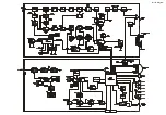
The speech signal from the microphone is delivered via
the MIC Jack to the RF Unit; after passing through
Q315
(
NJM2902V
) which consists of amplifier, pre-emphasis,
limiter (IDC instantaneous deviation control) and lowpass
filter, to
Q319
(
M6364FP
) which is adjusted for opti-
mum deviation level and delivered to the TX VCO
Q322
.
The speech signal from the microphone and CTCSS are
FM modulated by the TX VCO of the synthesizer, while
DCS audio is modulated by the reference frequency os-
cillator of the synthesizer.
Synthesizer output, after passing through diode switch
D311
(
1SS321
), is amplified by pri- drivers
Q317
(
2SC3356
) and
Q314
(
RD00HVS1
), driver
Q313
(
2SK3075
), and power amplifier
Q305
(
RD70HVS1
)
to obtain full RF output. The RF energy then passes
through antenna switch
D303
(
XB15A407
) and a low-
pass filter circuit and finally to the antenna connector.
RF output power from the final amplifier is sampled by
C318 and C324 and is rectified by
D302
(
1SS321
).
The resulting DC is fed through Automatic Power Con-
troller
Q309
(
UMT1N
),
Q312
(
DTC114
), and
Q311
(
2SB1197
) to transmitter RF amplifier
Q305
and is used
to provide control of the power output.
Generation of spurious products by the transmitter is min-
imized by the fundamental carrier frequency being equal
to the final transmitting frequency, modulated directly in
the transmit VCO.
Additionally harmonic suppression is provided by a low-
pass filter consisting of L303, L305, C303, C309, C310,
and C316, resulting in more than 60 dB of harmonic sup-
pression prior to delivery of the RF
Summary of Contents for FT-2800M
Page 4: ...4 Exploded View Miscellaneous Parts Note...
Page 5: ...Block Diagram...
Page 6: ...Block Diagram Note...
Page 13: ...COM Unit RF Unit Circuit Diagram...
Page 14: ...COM Unit RF Unit Circuit Diagram Note...
Page 18: ...18 Note...
Page 24: ...24 a b c d e f g 1 2 3 4 5 Side B 1SS312 D302 311 RF Unit Parts Layout Lot 1 15...
Page 28: ...28 a b c d e f g 1 2 3 4 5 Side B 1SS312 D302 311 RF Unit Parts Layout Lot 57...
Page 38: ...38 REF DESCRIPTION VALUE V W TOL MFR S DESIG VXSTD P N VERS LOT SIDE LAY ADR Note...
Page 39: ...13...


