background image

Transceiver Cloning 

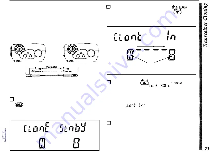
You  can transfer all data stored in one 

FT-51R 

to another set automatically by a cloning proce- 
dure. This requires a user-constructed cable to 

connect the 

EAR 

jacks on the two transceivers as 

shown below. 


Tip 

Tip 

Construct a clone cable and in- 

sert into the 

EAR 

jacks as shown. 

Turn both units off, then press and hold the 

key  of  each  radio  while  turning  the 

power  on again. The display appears as be- 
low. 

Now insert the clone cable into 

jack 

key on 

of  each tranceiver, and press the 
the 

destination 

FT-51R. 

Top 

segments move and inner segments rotate, indicating 

data transfer from source to destination transceiver. 

Next press the 

key on the 

FT-51R 

(the display shows 

After successful data transfer, the destination 

transceiver turns off automatically. If  there was a 
problem, 

appears on the display, re- 

check your cable and then turn both transceivers 
off  and try again. 

Remove the cloning cable. Channel and oper- 
ating data for both transceivers are now iden- 
tical. 

Summary of Contents for FT-51R

Page 1: ...FT 51R Dual Band FM Paging Transceiver...

Page 2: ...ges 19 21 Frequency Step Selection 20 Tuning Dual In Band Receive SpectrumScopeOperation 22 Transmitting 23 Duplex Operation 24 Sub channel Receiver Mute 26 Memory Skip Scanning PMS Scanning Priority...

Page 3: ...pmessages guide you through most operational function selec tions and settings even informingyou which battery pack type is installed DTMF and Message Paging with Morse Code Annunciator decodes incomi...

Page 4: ...elect are received In addition DTMF messages up to twelve characters long can be sent to other stations Received messages are displayed and automatically stored for later retrieval A tri mode ringer a...

Page 5: ...ion superheterodyne IFs 45 05 MHz 455 kHz VHF 58 525MHz 455 kHz UHF 12 dBSINADSensitivity 0 158 pV VHF 0 180 pV UHF Adjacent channel selectivity 65 dB VHF 60 dB UHF Intermodulation AF output 65 dB VHF...

Page 6: ...Hour Chargers NC 55B C for FNB 31 usew CA 9 NC 34B C for FNB 33 35 usew CA 9 NC 38B C for FNB 38 use w CA 9 B suffixfor use with 117VAC or C for use with 220 234 VAC CA 9 Base Charging Stand used w N...

Page 7: ...dust and water 3 MIC Jack This 2 conductor 2 5 mm phone jack accepts a optional microphone or speaker mic im pedance is 2 kQ The internal microphone is disabled while this jack is used 4 DIAL Rotary S...

Page 8: ...mentarily pressing first and then the desired key within fiveseconds There are also some Setting Mode func tions for customizing less commonly used features This mode is activated by pressing and hold...

Page 9: ...erated without removal Press and hold the PTT switchwhile speaking across the microphone opening to transmit the microphone element is at the panel bot tom While transmitting the VHF or UHF indicator...

Page 10: ...Paging Indicator PagingMessage DTMF Paging DTMF Code Rx DTMFPaging DTMFCode Function I D Rel Tx Pwr Full Duplex Rel Tx Pwr Autodialer LefVRightDisplay Information Separator for Memory ChannelDisplay...

Page 11: ...AMobile Power Adapter and an external DC voltage source Different 15 hour compact chargers are re quired for differentpacks seetable FNB 311 33 600 1200 NC 55B C FNB 35 i 1 900 1NC 34B C 1 FNB 38 600...

Page 12: ...nsceiver is not in use When the transceiver is inserted into the hanger an LED turns on to indicate charging is taking place and the transceiver display auto matically illuminates for easy night time...

Page 13: ...smoothly out of its track To open the FBA 14 battery case place your thumbs on the lugs on top of the case and gently pry the case apart Replace all four batteries noting the polarity indicated inside...

Page 14: ...a scanning hand loud speaker microphone with programmable func tion key and its own display A lamp switch turns onbacklight illumination for easyviewing in the dark Transceiver volume level can alsob...

Page 15: ...low Tx power Select the Low Tx power level set ting using the DIAL knob or a 1 I keys E L I or 3 Display and select the power saver interval sleep ratio use the DIAL knob or ml keys to select the desi...

Page 16: ...volume level Toggle Pagingnrigger PagindCode Squelch and CTCSS Bell Functions __ Alternate Function after pressing OM G I icon dis playedfor 5 secs _ From memory mode only toggle scan skip of current...

Page 17: ...with the functions of the controls Note especially the display on page 8 and key information on pages 13 14 63 When you press the front panel keys during reception one or two beeps sound to indicate k...

Page 18: ...high pitched beep when you press or a high pitched beep tgllpwed by a low pitched beep when you press m You can disable the beeper as described in the box but we recommend keeping it enabled while get...

Page 19: ...el press again to return control to the main channel VolumeSetting Pr sQL to select the desired band then press or to adjust receiver volume for that band While setting the volume illik is dis played...

Page 20: ...give some indication If several bargraph segments appear while the squelch is closed try reducing the squelch set ting if you want to hear weak signals In non European versions the monitor switch the...

Page 21: ...are in the memory mode The l I j l 7 1 1 1 I key switches from the VFO mode to the last used memory and switches from thememorymode to thelast usedVFO Whilein the memory mode your previous VFO mode s...

Page 22: ...e first key the display clears and only the new digit appears When you press the last key the display reverts to normal show ing the new operating frequency to 5 digits if it svalid or the originalfre...

Page 23: ...tions key entries will work To avoid this splinter tuning can be enabled seethe box on page 27 Tuning You can turn the DIAL or press cr m to tune in the selected step size If you press and hold a wkey...

Page 24: ...channels either side of the current channel number irrespectiveof their ac tual frequencies By default thyss ctrum scope is enabled by pressing OM 5 To have it automatically activate any time you rot...

Page 25: ...e rolling bargraph segments until changed B M DO F M BANDOFFr4 StarJtJwyeping for activity by either pressing or turning the DIAL Tune until you can see station activity then slowly turn the DIAL unti...

Page 26: ...0 90 0 80 1 20 1 10 1 35 1 50 20 mW 0 5 1 5 3 0 2 5 5 upper values are for VHF lower are UHF Note that all values listed are power level during setting and when transmit ting Press the PTT or wait 3...

Page 27: ...r cross band full duplex operation to reduce audio feedback 0 Select the desired mode by pressing QM a repeating as necessary for the corre sponding display indication DUP The microphone is located at...

Page 28: ...A MUTE TUV Repeater Splits The FT 51R offers three methods to set up split transmit receive operation for repeaters manual automatic and independently stored Tx Rx frequencies Both manual and automati...

Page 29: ...Press REV again to return to the normal shift direction RPTSEU Setting Standard Repeater Ofset The repeater offset is preset in version A only to 600 kHz for VHF and 5 7 6 or 1 2MHz for UHF To change...

Page 30: ...sceiver please refer to the chart shown be low The ARS function is enabled at the factory To disable it 0 Press OM J then rotate the DIAL so that SELC i5 RR5 5ET appears 0 Now you can press or to togg...

Page 31: ...ity with the limit of 35 regular memories SKIP 1 2 34 35 L1 u1 L2 u2 Memory Channel Organization These store frequency a n d o p e r a t i o n a l settings can also be maskedfrom viewing selection and...

Page 32: ...r data in memory 5 First set up the desired frequency and offset on the VFO seepage 18 for V2 second 0 blinks so the memory channel number is displayed then do the next step within 5 seconds 0 Hold MH...

Page 33: ...turn to the last used VFO press m Call Channel Memory The Call channel memory for each band can be instantly recalled by the button CRLL appears below the frequency display for the re spectiveband The...

Page 34: ...select a new memory if desired and press 0again momentarily Operation re mains on the new memory as the old memory reverts to its original state RPT NO SKIP 6 Once you have retuned a memory if 2 oy d...

Page 35: ...this point the lower dis play should clear except for u I blinking in the first character splace 0 Rotate the DIAL A character immediately ap pears blinking in the left most place of the display Cont...

Page 36: ...le beep sounds each time the scanner reaches the band edge unless thebeeper is disabled page16 Scanning resumes according to how you set the scan re sume mode described in the box to the right Scan Re...

Page 37: ...lso scan only between two frequencies of your choice with the selected channel steps The limits are stored in two pairs of special memories labeled L LI and L Ut 0 Store the lower edge of the desired...

Page 38: ...446 900and 446 995MHz SKIP SKIP Once the k U memory pairs are stored you can reactivate PMS scanning and tuning just by recalling any PMS memory and pressing again However you cannot activate the sub...

Page 39: ...ually press m Note that you can use any memory besides memory 1 as a priority channel in the above procedure when operating froma VFO You can not however switchVFOs or between memory and VFO operation...

Page 40: ...ll and DTMF Paging covered later 0 Press rotate theMEIeL for 5Et R T h l r L I U U L I I I h i l p andpress o r a toturnthe lamp function on off Press the PTT to save and exit DC Lamp When inserting t...

Page 41: ...is displayed TONE W With one press T encode appears at the top of the display and the tone genemtsr is activated for transmission Press O m a g a i n or just 1 if the alternate key functions are stil...

Page 42: ...equency 0 First activate CTCSS Tone Squench a and 1 again if necessary until T SQ appears 0 Press a to display a CTCSS fre 0 Hold aor for 1 2second to begin scan The scanning speed is rapid when no si...

Page 43: ......

Page 44: ...a as de scribed on the previous page Note T S Q does not have to be selected appear in this case 0 Press E four times to select the CTCSS Bell mode This cycles through the followingpag ing mode displa...

Page 45: ...matchthose stored in one of its code memories The squelchthen opens so the caller is heard and in the paging mode the LCD and keypad light as the paging ringer im mediately sounds seepage 56 When you...

Page 46: ...splay responds depends on which paging code was received The key to using DTMF paging in the FT 51R is first under standing how the Code Memories are used Code Memory P PersonalCode Memory You must ch...

Page 47: ...iverauto matically reverts to Code Memory C and dis plays the caller s ID If the paging code matches one of the other codes stored in Code Memories 1 9 the calling station s ID is still entered in Cod...

Page 48: ...DTMF paging ID code 0 Use the numeric keys to enter the three digits C E C you want to use for your ID then press or the PTT to return the display to the operat ing frequency Your personal ID code is...

Page 49: ...mal fre quency display by pressing As mentioned earlier in the CTCSS Bell procedure repeatedly pressing this key cycles through DTMF paging CODE C PAGEdisplayed trigger paging W A G E code squelch COD...

Page 50: ...place of the 100 s of MHzdigit if the One Touch Paging op tion is enabled and they will open the squelch of the other station Therefore at the start of each transmission you must wait a secondor two a...

Page 51: ...Memory number in place of the 100 s of MHz frequency digit whenever DTMF Code Squelch DTMF Paging or Trigger Paging is en abled the rest of the frcgugncy digits remain as before The i r and keys rapid...

Page 52: ...1 appears asshown below LOW 0 Toggle or I to step through the re sponse mode choices shown at the upper right side of the display 81 1 5 Answer Back F o 1 Page Forwarding F Automatic response disabled...

Page 53: ...to enter text as you would like it to appear The reserved ID slot uses the same format and is basicallyjust another message slot How ever when the receiving station is set up for message and ID recept...

Page 54: ...ers To do this 0 Press and hold the button for longer than 1 2 second one of the factory message shown at the left or another previously stored mes sage will appear in the lower display a until I d ap...

Page 55: ...the message and ID if se lected as it is being sent Sending Messages Manually If you do not have a particular message in memory or the time to store it you can send it manually by using keypad button...

Page 56: ...was received on and what slotitisnow stored in 1 9 Message Header Display Format LOW Message ID M2g received Messaie Slot Tx Rx enabled on UHF band Number 1 9 Next themessagetext slowlyscrollsacrossth...

Page 57: ...rocedure First recall the desired message by holding the button for hsecond and using the wbuttons Hold OM again for second then press to clear the message Message Storage After receiving ten incoming...

Page 58: ...ir message The DTMF Message ringer can be enabled or disabled However when enabled it only rings once when using the Morse annunciator The User Melody is stored in DTMF Auto Dial Memory 0 reserved for...

Page 59: ...to store As you do so theblinkingserialdigitsplace at the left side of the display increments automatically as the entered digits are displayed at bottom 0 Press and hold OM again for 1 2 second Sele...

Page 60: ...rs of the DTMF sequenceyou wish to store As you do so theblinkingserialdigitsplace at the left side of the display increments automatically as the entered digits are displayed at bottom I Selected DTM...

Page 61: ...s on the air first make sure the DTMF memory mode is activated is displayed Then close the PTT switch and simply press the number of the auto dial memory to transmit Once the DTMF sequence has begun y...

Page 62: ...n select and view this memory at any time to see what numberswere most recently dialed Composing the Ringer User Melody The default ringer with CTCSS Bell or DTMF Paging operation is factory programme...

Page 63: ...than 15 notes press eafter the last note to finish otherwise entry terminates automatically 0 You can press or to select another DTMF memory to store and repeat the last two steps or elsepress Q agai...

Page 64: ...okeep the PTT depressed This is convenient for re peater or personal autopatch operation when the number you are dialing isn t stored in a DTMF Auto dialer memory To enable this feature perform the fo...

Page 65: ...the autodial memoryto be named 3 Press OM for 112 sec then a 4 Use DIAL to choose characters press to enter Press to finish To name Channel Memories 1 Recall memorychannel to be named 2 Press OM for...

Page 66: ...elect normal long DTMFpagingTx delay 450 750 ms Enableldisable ARS Auto Repeater Shift SEt s PRGE 3LH 48 5Et IS RR5 5ET Select Paging ringer type internal user AI Morse 56 Enable disable Tx Power Save...

Page 67: ...e tablebelow For detailed explanationson how these affect transceiver operation refer to the page s listed in the far right column Enable Extended Receive 110 180MHz 420 470 MHz 61 74 Reset CPU and al...

Page 68: ...nd a timer starts every time you press a key If you don t press any keys for the selected time out period and us long as you arenot scanning or priority monitoring a will begin blinking and if you hav...

Page 69: ...rotating the DIAL to change the current displayed saver ratio Possible selectionsare shown in the table SAVE GHI TX Save A good operating habit is to use the lowest transmitter power necessaryto main...

Page 70: ...ess Beeper Disable The keypad beeper draws several milliam peres so you may want to disable it if you need to conservepower while using the keys a lot Do this by pressing OM then using theJ AL to sele...

Page 71: ...ng rechargeable batteries switch the transceiver off and recharge or replace the bat tery as soon as the indicator begins to blink Try to avoid recharging Ni Cd batteries often with little use between...

Page 72: ...ce Rememberthat theTx duty cyclewill probably be much greater than before so use a low Tx power output setting for cooler operation There are two cross band repeater selections one way repeat and bi d...

Page 73: ...d on The b automatically switches to 9 show which channel the FT 51R is transmit ting or else you can glance at the VHF UHF LEDs to see which is green red respectively 0 To exit the cross bandrepeater...

Page 74: ...display appears as be low 0 Now insert the clone cable into thg FAR jack key on of each tranceiver and press the the destination FT 51R Ir l I Top segments move and inner segments rotate indicating da...

Page 75: ...pplied with your TNC for final audio adjustments and operation To use the FT 51R for packet the power saver should be disabled since the sleep periods used in power saver operation cancausepacketsto b...

Page 76: ...frequency with the selectedrepeater shift is resulting in an out of bandTx frequency Invalid key entries usually do nothing and no beep sounds However if the keys are locked nothing happens when you p...

Page 77: ...roved modifi cations performed on the circuitry of this equipment may cause harmful interference and could result in damageto the transceiver With the exception of MARS MilitaryAffili ate Radio Servic...

Page 78: ...tos California 90703 U S A YAESU EUROPE B V Snipweg 3 1118DN Schiphol The Netherlands YAESU UK LTD Unit 2 Maple Grove Business Centre Lawrence Rd Hounslow Middlesex TW4 6DR UK Copyright 1994 Yaesu Mus...

Reviews: