background image

96

FT-857 Operating Manual

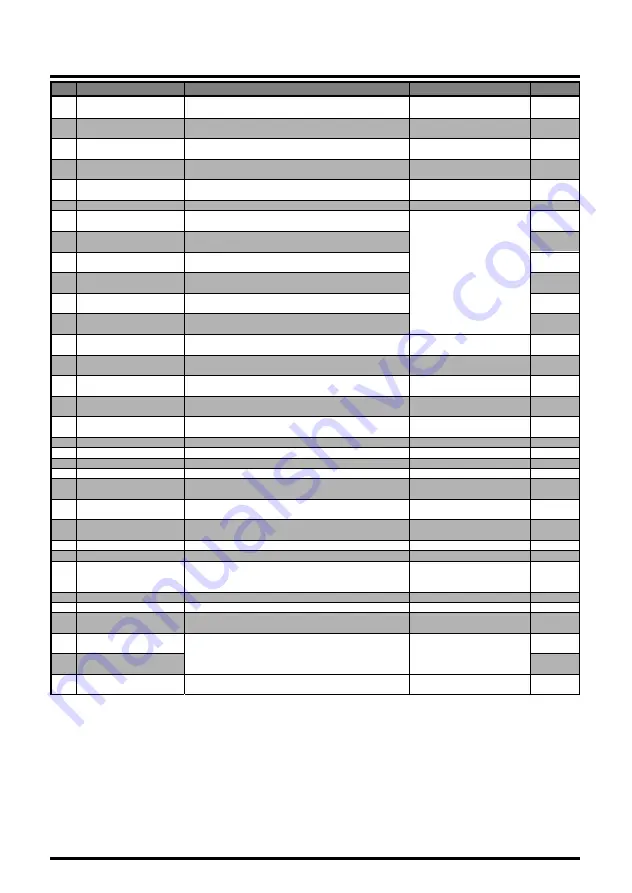
No

Menu Item

059 MIC SEL

060 MTR ARX SEL

061 MTR ATX SEL

062 MTR PEAK HOLD

063 NB LEVEL

064 OP FILTER 1
065 PG A

066 PG B

067 PG C

068 PG ACC

069 PG P1

070 PG P2

071 PKT 1200

072 PKT 9600

073 PKT RATE

074 PROC LEVEL

075 RF POWER SET

076 RPT SHIFT
077 SCAN MODE
078 SCAN RESUME
079 SPLIT TONE
080 SQL/RF GAIN

081 SSB MIC GAIN

082 SSB STEP

083 TONE FREQ
084 TOT TIME
085 TUNER/ATAS

086 TX IF FILTER
087 VOX DELAY
088 VOX GAIN

089 XVTR A FREQ

090 XVTR B FREQ

091 XVTR SEL

Function

The choice of the equipment which connects to the
MIC jack.
Select the analog meter display configuration while
the transceiver is receiving.
Selects the analog meter display configuration
while the transceiver is transmitting.
Enabling/disabling of the “peak hold” function of the
meter.
Setting of the blanking level for the IF Noise
Blanker.
Not available at this time.
Programming the [A] key (in the Operating
Function Row “q” (MFq)) function.
Programming the [B] key (in the Operating
Function Row “q” (MFq)) function.
Programming the [C] key (in the Operating
Function Row “q” (MFq)) function.
Programming the optional MH-59A8J microphone’s
[ACC] button assignment.
Programming the optional MH-59A8J microphone’s
[P1] button assignment.
Programming the optional MH-59A8J microphone’s
[P2] button assignment.
Adjusts the audio input level from the TNC during
1200 bps Packet operation.
Adjusts the audio input level from the TNC during
9600 bps Packet operation.
Sets the transceiver’s circuitry for the Packet baud
rate to be used.
Sets the compression level for the AF speech
processor in the SSB/AM modes.
Setting of the maximum power level for the current
band.
Sets the magnitude of the repeater shift.
Selects the desired Scan-Resume mode.
Sets the delay time for scanning resumption.
Enables/disables split CTCSS/DCS cording.
Selects the configuration of the front panel’s SQL/
RF knob.
Adjusts the microphone gain level for the SSB
mode.
Selects the tuning steps for the MEM/VFO CH
knob on the SSB mode.
Setting of the CTCSS  Tone Frequency.
Select the Time-Out Timer time.
Selects the device (FC-30 or ATAS-100/-120) to be
controlled via the front panel’s [A](TUNE) key.

Selects the Transmit IF filter.
Sets the “hang time” for the VOX circuitry.
Sets the gain of the VOX circuitry’s input audio
detector.
Allows an arbitrary frequency to be set on the
display, to allow direct frequency readout during
transverter operation.

Enables/disables/selects the antenna port to be
used for Transverter operation.

Available Values

NOR/RMT/CAT

SIG, CTR, VLT, N/A, FS,
OFF
PWR, ALC, MOD, SWR,
VLT, N/A, OFF
ON/OFF

0 ~ 100

All Multi Function,
All Menu Item, MONI,
Q.SPL, TCALL, ATC and
USER.

0 ~ 100

0 ~ 100

1200/9600 (bps)

0 ~ 100

5 ~ 100
2 ~ 100 (UHF)
0.00 ~ 99.99 (MHz)
TIME/BUSY/STOP
1 ~ 10 (sec)
ON/OFF
RF-GAIN/SQL

0 ~ 100

1kHz/2.5kHz/5kHz

50 Standard CTCSS tones
OFF/1 ~ 20 (min)
OFF/ATAS(HF)/
ATAS(HF&50)/ATAS(ALL)/
TUNER
CFIL/FIL1/FIL2
100 ~ 3000 (ms)
1 ~ 100

0,000,00 ~ 9999,999,00
(kHz)

OFF/X VTR A/X VTR B

Default

NOR

SIG

PWR

ON

50

MONI

Q. SPL

ATC

MONI

Q. SPL

TCALL

50

50

1200 bps

50

ø

2

ø

2

TIME
5 sec

OFF

ø

1

50

2.5kHz

88.5 Hz

OFF
OFF

CFIL

500 ms

50

OFF

M

ENU

 O

PERATION

ø

1: Depends on transceiver version.

ø

2: Depends on operating band and transceiver version.

Summary of Contents for FT-857 series

Page 1: ...CA 90630 U S A International Division 8350 N W 52nd Terrace Suite 201 Miami FL 33166 U S A YAESU EUROPE B V P O Box 75525 1118 ZN Schiphol The Netherlands YAESU UK LTD Unit 12 Sun Valley Business Park...

Page 2: ...8 DCS Operation 59 DCS Search Scanning 59 Split Tone Operation 60 ARTSTM Operation 61 CW Identifier Setup 62 Digital Mode Operation SSB Based AFSK 63 RTTY Radio Tele Type Operation 63 PSK31 Operation...

Page 3: ...ong the advanced features of the FT 857 are many incorporated only in large base station transceivers These include Dual VFOs Split Frequency operation Digital Signal Processing Bandpass Filtering Noi...

Page 4: ...warmup with optional TCXO 9 Supply Voltage Normal 13 8 VDC 15 Negative Ground Current Consumption Squelched 550 mA Approx Receive 1 A Transmit 22 A Case Size W x H x D 6 1 x 2 0 x 9 2 155 x 52 x 233...

Page 5: ...CW AM FM 100 kHz 1 8 MHz 1 8 MHz 28 MHz 2 5 V 28 MHz 30 MHz 2 5 V 0 32 V 50 MHz 54 MHz 1 V 0 16 V 144 430 MHz 0 5 V 0 16 V Image Rejection HF 50 MHz 70 dB 144 430 MHz 60 dB IF Rejection 60 dB Selectiv...

Page 6: ...llins CW Filter 500 Hz 2 kHz 6 dB 60 dB YF 122CN Collins CW Filter 300 Hz 1 kHz 6 dB 60 dB TCXO 9 TCXO Unit 0 5 ppm MD 200A8X Desktop Microphone MH 36E8J DTMF Microphone MH 59A8J Remote Control Microp...

Page 7: ...ocal dealer if the unit was purchased over the counter so as to get instructions regarding the prompt resolution of the damage situation Be certain to save the shipping carton especially if there are...

Page 8: ...d or to each other Do not stand in front of a directional antenna while you are transmitting into that antenna Do not install a directional antenna in any location where humans or pets may be walking...

Page 9: ...r Just route the cable into the appropriate channel provided as shown in the illustration 3 Connect the Control cable between the Front Panel and Transceiver Body 4 Install the Front Panel by sliding...

Page 10: ...erminal In mobile installations noise pickup may be minimized by connecting the DC cable directly to your vehicle s battery rather than to the ignition switch or accessory circuitry Direct connection...

Page 11: ...Check the battery terminal connections frequently to be sure they are tight and not cor roded r When operating with the vehicle turned off or operating from a stand alone car battery in a camp site e...

Page 12: ...xial cable shield it is often recommended that you provide a direct ground connection to the vehicle chassis at the mounting location of the transceiver installation using the MMB 82 Mounting Bracket...

Page 13: ...ates a serious risk of explosion Inside the station a common ground bus consisting of a copper pipe of at least 1 25 mm diameter should be used An alternative station ground bus may consist of a wide...

Page 14: ...sceiver on the 1 8 50 MHz bands so long as the SWR on the coaxial line connected to the FC 30 is below 3 1 On the VHF and UHF bands coaxial line losses increase so rapidly in the presence of SWR that...

Page 15: ...o have higher losses than larger diameter cables although the precise differences depend on the cable construction materials and the quality of the connectors used with the cable See the cable manufac...

Page 16: ...to radio frequency en ergy Compliance is based on the actual power output used feedline loss antenna type and height and other factors which can only be evaluated as a system Information regarding th...

Page 17: ...chokes may be required on interconnecting patch data cables As a last re sort you can try installing additional shielding within the computer s case using appropri ate conductive mesh or conductive s...

Page 18: ...is the ground return The ring connection of the ACC jack when closed to ground places the FT 857 into the transmit mode and sends a steady CW carrier for amplifier or antenna tuner adjustment purpose...

Page 19: ...mmonly available keyer paddles should work perfectly with the built in Electronic Keyer The wiring configuration for the paddle is shown below INSTALLATION LINEAR AMPLIFIER INTERFACING For straight ke...

Page 20: ...inal Pin 5 and Ground Pin 2 The audio output is fixed at 100 mV with an impedance of 600 W ADJUSTING THE FRONT FEET The two front feet of the transceiver allow the transceiver to be tilted upward for...

Page 21: ...19 FT 857 Operating Manual INSTALLATION NOTE...

Page 22: ...h SELECT knob This detented rotary switch is used for VFO frequency tuning memory selection and function selection for the A B C keys of the transceiver HOME Key Pressing this key momentarily recalls...

Page 23: ...for the optional receiver s Digital Signal Pro cessing system The available functions will appear as the functions displayed above the A B and C keys as described previously Pressing this key once mor...

Page 24: ...stems Press and hold in this key to store the contents of the VFO into the QMB Quick Memory Bank register LOCK Key Pressing this key locks the front panel keys so as to prevent accidental frequency ch...

Page 25: ...andard Please refer to the MENU No 060 and No 061 SP PH Jack This 3 5 mm 2 pin jack provides variable audio output for an external speaker 4 W 16 W impedance or earphones The audio level varies accord...

Page 26: ...t the two VFOs contents will be identi cal C Key SPL Press the C SPL key to activate Split frequency operation between VFO A and VFO B Multi Function Row b MFb MW SKIP TAG A Key MW Press this key mome...

Page 27: ...ction Row d MFd RPT REV VOX A Key RPT Press the A RPT key to select the direction of the uplink frequency shift or simplex during FM repeater operation Press and hold in the A RPT key for one second t...

Page 28: ...recall Menu Mode No 033 DCS CODE for selecting the DCS code C Key TDCH Press the C TDCH key to initiate CTCSS Tone or DCS Search Multi Function Row f MFf ARTS SRCH PMS A Key ARTS Press the A ARTS key...

Page 29: ...Key MTR Pressing the A MTR key repeatedly allows selection of the display function of the meter in the transmit mode PWR ALC SWR MOD PWR The selected function will appear above the B key Press and ho...

Page 30: ...C 30 Automatic Antenna Tuner or ATAS 100 120 Active Tuning Antenna System Press and hold in the A TUNE key for one second to initiate tuner or antenna retuning B Key DOWN Press and hold in the B DOWN...

Page 31: ...Key Press the B key to select the optional IF filter which is located on the FIL 1 Optional Filter 1 slot on the Main Unit When an optional filter is not installed on the FIL 1 slot this key function...

Page 32: ...ckwise will select Menu Mode No 046 for adjustment of the low frequency cutoff frequency In the CW mode press and hold in the C DBF key for one second to recall Menu Item No 045 DSP BPF WIDTH for sett...

Page 33: ...31 FT 857 Operating Manual FRONT PANEL CONTROL SWITCHES NOTE...

Page 34: ...ovides an Transmit Power Control terminal If you connect pin 3 BATT SENS of the DC power jack to the ground the FT 857 automatically switches to 20 Watts 430 MHz 10 Watts of output power CAT LINEAR Ja...

Page 35: ...ier for linear amplifier or manual antenna tuner adjustment KEY Jack This 3 5 mm 3 pin jack is used for connection to a CW keyer paddle or a straight key EXT SPKR Jack This 3 5 mm 2 pin jack provides...

Page 36: ...set frequency steps and operating modes You can change the channel steps and operating mode once you get started of course per the next section To change the frequency band press either the BAND DWN o...

Page 37: ...ll discussion of the Menu system begins on page 94 for now here is a brief discussion on how to change Menu settings 1 Press and hold in the FUNC key for one second to enter the Menu mode 2 Rotate the...

Page 38: ...function solely as a Squelch control In this case rotate the SQL RF Gain control to the point where the back ground noise is just silenced this will provide the best sensitivity to weak signals while...

Page 39: ...engage the Fast Tuning mode just press the POWER switch momentarily while the transceiver is on You will observe a small icon in the bottom right hand corner of the LCD and as you rotate the main tun...

Page 40: ...tting to ON to enable the extended Menu Mode 3 Rotate the SELECT knob so as to recall No 054 LOCK MODE 4 Rotate the DIAL to select the desired configuration DIAL Locks DIAL knob only FREQ Locks front...

Page 41: ...within 1 kHz or beyond 1 kHz icon will appear to the right of the frequency display When the receiving frequency is equal to transmit frequency Clarifier offset is zero while the Clarifier is activate...

Page 42: ...e IF SHIFT s cur rent position 2 Rotate the SELECT knob as needed to reduce or elimi nate the interference 3 To turn the IF SHIFT feature off again press and hold in the CLAR button for one second The...

Page 43: ...seful in reducing or eliminating some types of impulse noise especially noise generated by automotive ignition systems 1 Press the FUNC key momentarily then rotate the SELECT knob as needed until Mult...

Page 44: ...ubstantial protection against intermodulation and other problems associated with strong signal input to the receiver Rule of thumb so long as the S meter is moving on background noise additional front...

Page 45: ...e the bandwidth to your operating needs To adjust the Low Cut and High Cut characteristics of the DSP Bandpass Filter Press and hold in the C DBF key for one second This instantly activates Menu Mode...

Page 46: ...NOISE REDUCTION DNR REQUIRES OPTIONAL DSP 2 UNIT The Noise Reduction feature of the DSP system may be used to enhance signal to noise ratio on weak signals 1 Press the DSP key momentarily This instan...

Page 47: ...n the Notch Filter off Do not activate this filter in the CW mode as incoming CW signals will be notched out of the audio passband AM FM TUNING DIAL OPERATION In the AM and FM modes the DIAL knob is l...

Page 48: ...the desired time period after which the radio will auto matically shut down 4 Press and hold in the FUNC key for one second to save the new setting and exit to normal operation Once you have programme...

Page 49: ...47 FT 857 Operating Manual RECEIVER ACCESSORIES NOTE...

Page 50: ...econd to enter the Menu mode Rotate the SELECT knob to recall Menu Mode No 081 SSB MIC GAIN on SSB or No 005 AM MIC GAIN on AM Close the PTT switch and while speaking into the microphone rotate the DI...

Page 51: ...ess and hold in the C VOX key for one second This is a hot key feature which will instantly recall Menu Mode No 088 VOX GAIN While speaking into the microphone rotate the DIAL to the point where the t...

Page 52: ...sion Level may be adjusted via the Menu as follows While still in Multi Function Row c STO RCL PROC press and hold in the C PROC key for one second This instantly recalls Menu Mode No 074 PROC LEVEL R...

Page 53: ...ristics To set up the DSP Microphone Equalizer feature 1 Press and hold in the DSP key for one second This instantly activates Menu Mode No 048 DSP MIC EQ 2 Rotate the DIAL to select one of the follow...

Page 54: ...old in the FUNC key for one second to enter the Menu mode Rotate the SELECT knob to Menu Mode No 024 CW DELAY Rotate the DIAL to select a longer or shorter delay time default 250 ms If the delay selec...

Page 55: ...available offset range is 400 800 Hz default value is 700 Hz When done press and hold in the FUNC key for one second to save the new setting and exit to normal operation 9 The FT 857 also has a CW SPO...

Page 56: ...o 030 CW SPEED Press the SELECT knob if you wish to select display of cpm characters per minute instead of wpm words per minute The cpm selection is based on the interna tional PARIS standard which st...

Page 57: ...e No 001 EXT MENU then rotate the DIAL to change the setting to ON to enable the extended Menu Mode if needed Rotate the SELECT knob to select Menu Mode No 025 CW KEY REV Rotate the DIAL knob to selec...

Page 58: ...hold in the FUNC key for one second to enter the Menu mode 5 Rotate the SELECT knob to recall Menu Mode No 001 EXT MENU then rotate the DIAL to change the setting to ON to enable the extended Menu Mod...

Page 59: ...d This instantly recalls Menu Mode No 076 RPT SHIFT Rotate the DIAL knob to select the desired shift frequency When done press and hold in the FUNC key for one second to save the new setting and exit...

Page 60: ...front panel s HOME key to transmit the burst tone FM mode only Tone Search Scanning In operating situations where you don t know the CTCSS tone being used by another station you can command the radio...

Page 61: ...disappear DCS Search Scanning In operating situations where you don t know the DCS code being used by another station you can command the radio to listen to the incoming signal and scan in search of t...

Page 62: ...u can see the following additional parameters T T Encodes a CTCSS Tone and Decodes a CTCSS Tone T D Encodes a CTCSS Tone and Decodes a DCS Code T CTCSS Tone Encode only D DCS Encode only D T Encodes a...

Page 63: ...ration press the A ARTS key again the out range or in range indication will disappear from the LCD ARTS Alert Beep Options The ARTS feature allows two kinds of alert beeps with the additional option o...

Page 64: ...de No 010 ARTS IDW 4 Press the SELECT knob momentarily to initiate callsign storage the first character location of the callsign field will be underlined 5 Rotate the DIAL knob to select the first let...

Page 65: ...RTTY L or RTTY U see discussion below 5 Press and hold in the FUNC key for one second to save the new setting and exit Use this basic technique to set up any digital mode RTTY Radio TeleType Operation...

Page 66: ...TTY operation Because RTTY is a continuous duty transmission mode try to keep your trans missions short when running on battery power so as to minimize current drain PSK31 Operation Two dedicated PSK3...

Page 67: ...9600 BPS FM OPERATION The FT 857 is designed for operation on either 1200 bps or 9600 bps packet and setup is similar to that described previously for SSB based modes A separate Data input adjustment...

Page 68: ...ith the optimum deviation being between 2 5 kHz and 3 5 kHz WEATHERFAX MONITORING Monitoring of HF WeatherFax broadcasts is easily accomplished using the FT 857 Before proceeding be certain that the W...

Page 69: ...ituation on the 20 meter band with a DX station transmitting on 14 025 MHz listening 10 kHz higher in the band 1 Set VFO A to 14 035 00 MHz CW DX station s listening frequency 2 Press the FUNC key mom...

Page 70: ...0 on the HF bands only with a dual band VHF UHF antenna connected separately to the 144 430 MHz antenna port no 50 MHz operation make the setting ATAS HF 4 Press and hold in the FUNC key for one secon...

Page 71: ...C UP or B DOWN key then release the PTT key to return to the receive mode R F Says 1 Once automatic matching has been successfully accomplished you must change frequency by at least 10 kHz before atte...

Page 72: ...A TUNE key repeatedly The transceiver will remain in the receive mode as it retracts this may take up to one minute Thereafter the transmitter will be engaged and the ATAS 100 120 will be automatical...

Page 73: ...T 857 before changing the Menu Mode item No 020 CAT LIN TUN 6 Press and hold in the FUNC key for one sec ond to activate the Menu mode 7 Rotate the SELECT knob to re call Menu Mode N o 0 8 5 TUNER ATA...

Page 74: ...e the SWR is above 3 1 2 1 on the 50 MHz band the tuning process will stop and no memory data will be stored However you may wish to move frequency a few kHz then press the A TUNE key again for one se...

Page 75: ...emory Pressing the A STO key momentarily while in Multi Function Row c STO RCL PROC will also store a frequency into the QMB register QMB Channel Recall 1 Press the FUNC key momentarily then rotate th...

Page 76: ...want to program in the frequency data press and hold in the A MW key for one second until you hear two beeps a second apart the second beep confirms that the frequency information was successfully sto...

Page 77: ...SELECT knob to select the channel on which you wish to store the receive frequency data 4 Press and hold in the A MW key for one second until you hear two beeps a second apart which confirms that the...

Page 78: ...d frequency as though you were in the VFO mode Just rotate the DIAL knob the Memory Channel Number will be replaced by one which indicates MTUNE indicat ing that you have now shifted into the Memory T...

Page 79: ...nob to select the memory channel to be deleted 3 Press the B MCLR key momentarily The frequency display field on the LCD will go blank and the memory channel number will blink 4 Wait about five second...

Page 80: ...channel location As usual you will hear a double beep to confirm the suc cessful storage of the frequency data 5 If you wish to store a Split frequency pair into the Home channel store the Receive fr...

Page 81: ...elect the first character in the name you wish to store then rotate the SELECT knob clockwise to move to the next character Note that both upper and lower case letters are available 7 Again rotate the...

Page 82: ...indicated on the display 5 While the Spectrum Scope is activated in the VFO mode press the B WID key to change the visible bandwidth Available selections are 10 default 15 and 63 channels Press the C...

Page 83: ...arch feature is available on the VFO mode only 3 Press the FUNC key momentarily then rotate the SELECT knob as needed until Multi Function Row f ARTS SRCH PMS appears on the display 4 Now press the B...

Page 84: ...PMS will be described later 3 Press the FUNC key momentarily then rotate the SELECT knob as needed until Multi Function Row g SCN PRI DW appears on the display 4 Wait at least five seconds until the M...

Page 85: ...activate the Menu mode 2 Rotate the SELECT knob to recall Menu Mode No 001 EXT MENU then rotate the DIAL to change the setting to ON to enable the extended Menu Mode 3 Rotate the SELECT knob to select...

Page 86: ...one at a time and you will observe that the Skipped channels are nonetheless available for recall by manual means 7 You may restore a previously skipped channel to the scanning loop by selecting the c...

Page 87: ...LECT knob as needed until Multi Function Row g SCN PRI DW appears on the display 4 Press the B PRI key momentarily to start the Priority monitoring feature the icon will appear at the upper of the fre...

Page 88: ...are now limited within the range between the selected PMS memory pair keeping operation inside this programmed range Example Limit tuning and scanning to the frequency range 144 30 148 00 MHz to pre...

Page 89: ...all VFO A then rotate the SQL control until the background noise is just silenced 3 Press the FUNC key momentarily then rotate the SELECT knob as needed until Multi Function Row g SCN PRI DW appears o...

Page 90: ...gency communication on this spot frequency is now possible 6 Press the V M keys as necessary to enter the Memory mode then rotate the SELECT knob to select the emergency channel M EMG which is found b...

Page 91: ...7 Press the B STRT key to generate another code group as above 8 To disable the CW Training feature press and hold in the FUNC key for one second to exit to normal operation You may adjust the Morse s...

Page 92: ...ish to store then rotate the SELECT knob one click clockwise to move to the next character 6 Repeat step 5 as many times as necessary to complete the Beacon Text If the Beacon Text is less than 40 cha...

Page 93: ...as the repetitive bea con text 7 To stop a repeating beacon message just press the A PLY1 key momentarily 8 To disable transmission from the Beacon just repeat the above procedure rotating the DIAL t...

Page 94: ...nd hold in the FUNC keyn for one second to exit the Menu mode Display Contrast The LCD s contrast may be adjusted using the Menu Mode as well 1 Press and hold in the FUNC key for one second to activat...

Page 95: ...to select the desired operat ing status which you wish utilize The default selections are ARTS The color changes depending on the In Range or Out of Range status BAND The color changes according to th...

Page 96: ...02 144MHz ARS 003 430MHz ARS 004 AM FM DIAL 005 AM MIC GAIN 006 AM STEP 007 APO TIME 008 ARTS BEEP 009 ARTS ID 010 ARTS IDW 011 BEACON TEXT 1 012 BEACON TIME 013 BEEP TONE 014 BEEP VOL 015 CAR LSB R 0...

Page 97: ...ophone equalization pattern Setting of the degree of DSP Noise Reduction Enables Tx Rx operation on the Alaska Emergency Channel 5167 5 kHz Adjusts the microphone gain level for the FM mode Selects th...

Page 98: ...he Packet baud rate to be used Sets the compression level for the AF speech processor in the SSB AM modes Setting of the maximum power level for the current band Sets the magnitude of the repeater shi...

Page 99: ...and Available Values ON OFF Default ON depending on transceiver version MENU MODE No 004 AM FM DIAL Function Enabling disabling of the DIAL knob on the AM and FM modes Available Values ENABLE DISABLE...

Page 100: ...callsign will be underlined 2 Rotate the DIAL knob to select the first letter number of your callsign then rotate the SELECT knob one click clockwise to save the first letter number and move to the n...

Page 101: ...able Values 300 300 Hz Default 0 Hz MENU MODE No 016 CAR LSB T Function Sets the Tx Carrier Point for LSB Available Values 300 300 Hz Default 0 Hz MENU MODE No 017 CAR USB R Function Sets the Rx Carri...

Page 102: ...LSB AUTO Default USB USB Injects the CW carrier oscillator on the USB side LSB Injects the CW carrier oscillator on the LSB side AUTO Injects the CW carrier oscillator on the LSB side while operating...

Page 103: ...n using the internal keyer Available Values 10 15 20 25 30 ms Default 10 ms Note If you select 25 or 30 ms please do not attempt to set Menu No 030 CW SPEED to a speed faster than 50 42 wpm as the del...

Page 104: ...cting COARSE doubles the tuning rate compared to the default value FINE 10 Hz step SSB CW mode 100 Hz step AM FM COARSE 20 Hz step SSB CW mode 200 Hz step AM FM MENU MODE No 036 DIG DISP Function Defi...

Page 105: ...USER L or USER U mode operation Available Values 3000 3000 Hz Default 0 Hz MENU MODE No 040 DIG VOX Function Sets the gain of the VOX circuitry s input level for the DIG mode Available Values 0 100 D...

Page 106: ...PF CUTOFF Function Adjusts the low cut characteristics of the DSP HPF filter Available Values 100 160 220 280 340 400 460 520 580 640 700 760 820 880 940 1000 Hz Default 100 This Menu Item determines...

Page 107: ...nd between the Memory channel M P5U and M 001 Use of this frequency is restricted to amateurs operating in or within 50 nautical miles 92 6 km of the U S State of Alaska and it is to be used for emerg...

Page 108: ...ed a label 2 Press and hold in the FUNC key for one second to enter the Menu mode 3 Rotate the SELECT knob to recall Menu Mode No 056 MEM TAG 4 Press the SELECT knob to enable the programming of the l...

Page 109: ...59A8J Remote Microphone CAT CAT system if you are using the optional FC 30 antenna tuner you can still use the CAT system by connecting the serial Data cable to the MIC jack MENU MODE No 060 MTR ARX...

Page 110: ...063 NB LEVEL Function Setting of the blanking level for the IF Noise Blanker Available Values 0 100 Default 50 MENU MODE No 064 OP FILTER 1 Not available at this time MENU MODE No 065 PGA Function Pr...

Page 111: ...Q SPL TCALL ATC and USER Default TCALL MENU MODE No 071 PKT1200 Function Adjusts the audio input level from the TNC during 1200 bps Packet operation Available Values 0 100 Default 50 MENU MODE No 072...

Page 112: ...er will hold until the signal disappears then will resume after one second STOP The scanner will stop when a signal is received and will not restart MENU MODE No 078 SCAN RESUME Function Sets the dela...

Page 113: ...and 50 MHz amateur band ATAS ALL The A TUNE key will activate the optional ATAS 100 120 on the HF VHF 6 2 m and 430 MHz bands TUNER The A TUNE key will activate the optional FC 30 MENU MODE No 086 TX...

Page 114: ...to allow direct frequency readout during transverter operation can also be used to account for frequency conversion inaccuracies when a known reference frequency is known Available Values 00 000 00 99...

Page 115: ...62 is a connection cable for the FT 857 and your computer The CT 62 has a built in level converter allowing direct connection from the rear panel CAT LINEAR jack to the serial port of your computer w...

Page 116: ...ecting the appropriate instruction opcode organizing the parameters as needed and providing unused dummy argument bytes to pad the block to its required five byte length the dummy bytes can contain an...

Page 117: ...P1 03 CWR P1 04 AM P1 08 FM P1 88 FM N P1 0A DIG P1 0C PKT CMD 05 CLAR ON CMD 85 CLAR OFF P1 00 OFFSET P1 00 OFFSET P3 P4 CLAR Frequency 12 34 12 34 kHz Toggle CMD 02 SPLIT ON CMD 82 SPLIT OFF P1 09...

Page 118: ...MHz 1MHz 100kHz 100 10Hz 10 1kHz 43 97 00 00 00 LSB 01 USB 02 CW 03 CWR 04 AM 06 WFM 08 FM 88 NFM 0A DIG 0C PKT 82 CW N CAT OPERATION 7 6 5 4 3 2 1 0 PO Meter Data Dummy Data SPLIT Status 0 SPLIT ON 1...

Page 119: ...factory default values Menu 06 AM STEP 33 DCS CODE 52 FM STEP 56 MEM TAG 76 RPT SHIFT 82 SSB STEP and 83 TONE FREQ r FUNC POWER on Resets all menu settings except the following menu items to their fa...

Page 120: ...io while turning the power on again The CLONE MODE notation will appear on the display 3 On the destination radio press the A RCV key 4 Now on the source radio press the C SEND key Data will now be tr...

Page 121: ...rews affixing the top cover of the transceiver then disconnect the speaker s connector from the MAIN Unit 3 Refer to Figure 2 locate the empty 16 pin connector and connect the DSP 2 here 4 Move the sm...

Page 122: ...stalled filter 4 Replace the top cover and its seven screws remember to replace the internal speaker s plug 5 Filter installation is now complete Connect the DC cable to the INPUT jack To use the opti...

Page 123: ...f the transceiver then disconnect the speaker s connector from the MAIN Unit 3 Referring to Figure 2 locate the factory installed REF UNIT on the board Remove the factory installed REF UNIT from the b...

Page 124: ...uency Memory storage technique described on page 42 First press the FUNC key momentarily then rotate the SELECT knob to select Multi Function Row a A B A B SPL Press the A A B key if necessary to sele...

Page 125: ...mory storage pro cess selecting memory channel M 002 this time when initially storing the 435 075 MHz receiving frequency Now repeat this entire process three more times filling memory channels M 003...

Page 126: ...ON TAG to label each satellite memory for example UO 14a UO 14e for the above five channels A complete set of frequencies may be stored for each LEO satellite you wish to utilize and once configured t...

Page 127: ...operation MH 59A8J Switches and Control LOCK Switch Pressing this key locks the FT 857 s front panel keys so as to prevent accidental frequency change PTT Switch Press this switch to transmit and rel...

Page 128: ...een the VFO and Memory Sys tems This key generates the DTMF 7 tone during transmission and frequency entry digit 7 during Direct Keypad Frequency Entry 8 DWN BAND key Pressing this key causes the freq...

Page 129: ...erates the DTMF B tone during transmission C key This key emulates the function of the FT 857 s front panel C key This key generates the DTMF C tone during transmission F D key Press this key momentar...

Page 130: ...ment SEL DIAL key and Indicator The SEL key switches the synthesizer steps of the SEL knob between the fine tuning same as DIAL knob step and coarse tuning same as SEL knob step modes When the fine tu...

Page 131: ...quipment is incapable of tuning or readily being altered by the User to operate within the frequency bands allocated to the Domestic public Cellular Telecommunications Service in Part 22 WARNING MODIF...

Page 132: ...Printed in Japan Copyright 2002 VERTEX STANDARD CO LTD All rights reserved No portion of this manual may be reproduced without the permission of VERTEX STANDARD CO LTD 0212u AK E H 0 0 7 M 1 0 0...

Reviews: