11
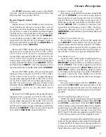
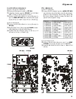
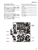
Local Oscillator Adjustment
Reference Frequency Adjustment
r
Connect the frequency counter to
TP1032
.
r
Adjust the trimmer capacitor (
TC5001
) for 67.875000
MHz (± 10 Hz) on the frequency counter.
r
Connect an RF millivoltmeter or an oscilloscope to
pin 2 of
J5002
(
TP1032
) and confirm that the output
level is 115 mv (± 30 mV) rms or 315 mv (± 80mV) p-p.
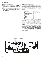
3ad Local Adjustment
r
Connect an RF millivoltmeter or an oscilloscope to
TP1037
.
r
Key the transceiver on CW, and adjust
T1025
for maxi-
mum indication on the RF millivolt-meter.
r
Confirm that the indicated voltage is 100 mv (± 30
mV) rms or 300 mv (± 100mV) p-p.
PLL Adjustment
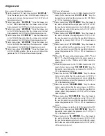
VCO VCV Adjustment
r
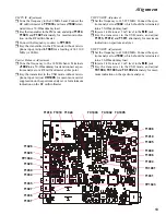
Connect the DC voltmeter to pin 6 of
J2002
(
TP1028
)
and, referring to the table below, tune the transformer/
inductor on each frequency listed. Then confirm that
the correct voltage is present, or adjust the listed com-
ponent for the required voltage.
Tune to :
Adjust / Confirm
For
13.895 MHz
Adjust T2001
5.5V ±0.5V
76.000 MHz
Confirm
At least 0.8V
32.995 MHz
Adjust T2002
5.5V ±0.5V
13.900 MHz
Confirm
At least 0.8V
55.995 MHz
Adjust T2003
5.5V ±0.5V
88.000 MHz
Confirm
At least 0.8V
163.995 MHz
Adjust L2010
5.5V ±0.5V
118.000 MHz
Confirm
At least 0.8V
469.995 MHz
Adjust L2011
5.5V ±0.5V
420.000 MHz
Confirm
At least 0.8V
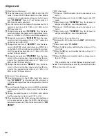
1st Local Output Level
r
Connect the RF millivoltmeter to pin 11 of
J2002
(
TP1029
), and set the transceiver to 28.000 MHz.
r
Confirm that the RF level is at least +3 dBm or 300
mV rms.
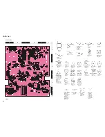
TP1032
TP1037
T1025
TP1028
TC5001
TP1029
Alignment
Summary of Contents for FT-897
Page 5: ...Block Diagram 5...
Page 6: ...Block Diagram 6 Note...
Page 21: ...21 MAIN Unit Circuit Diagram...
Page 22: ...22 MAIN Unit Note...
Page 52: ...52 MAIN Unit Note...
Page 59: ...59 PA Unit Circuit Diagram...
Page 60: ...60 PA Unit Note...
Page 73: ...73 PANEL Unit Circuit Diagram...
Page 74: ...74 PANEL Unit Note...
Page 75: ...75 PANEL Unit H Parts Layout Side A 1 2 3 F A C B E D BRPG1211C D4007 4010 4012 G...


