From December 2010 QST © ARRL
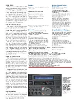
Table 1
Yaesu FT
DX
5000, serial number 00020034
Manufacturer’s Specifications
Measured in the ARRL Lab
Frequency coverage: Receive, 0.03-60 MHz;
Receive and transmit, as specified.
transmit, 1.8-2, 3.5-4, 5.3305, 5.3465, 5.3665,
5.3715, 5.4035, 7-7.3, 10.1-10.15, 14-14.35,
18.068-18.168, 21-21.44, 24.89-24.99, 28-29.7,
50-54 MHz.
Power consumption at 117 V ac: receive,
Receive, no signal, 61 VA; receive signal
no signal, 70 VA; signal present, 80 VA,
present, max audio, 66 VA; transmit,
transmit, 200 W output, 720 VA.
481 VA at 200 W RF output.
Modes of operation: SSB, CW, AM, FM, RTTY,
As specified.
PKT.
Receiver
Receiver Dynamic Testing,
Receiver “A”
SSB/CW sensitivity: 2.4 kHz bandwidth,
Noise floor (MDS), 500 Hz bandwidth,
10 dB S+N/N: 0.5-1.8 MHz, 2.0 µV;
600 Hz roofing filter:
1.8-30 MHz, 0.2 µV (Amp 2); 50-54 MHz,
Preamp
Off
1
2
1.25 µV (Amp 2). Preamp not available
(dBm) (dBm) (dBm)
below 1.8 MHz.
0.137 MHz –116 —
—
0.505 MHz –117 —
—
1.0 MHz
–118 —
—
3.5 MHz
–126 –136 –143
14 MHz
–126 –136 –142
50 MHz
–120 –131 –140
Noise figure: Not specified.
14 MHz, preamp off/1/2: 21/11/5 dB
AM sensitivity: 6 kHz bandwidth, 10 dB S+N/N:
10 dB (S+N)/N, 1-kHz, 30
%
modulation,
0.5-1.8 MHz, 6 µV; 1.8-30 MHz, 2 µV (Amp 2); 9 kHz filter, 15 kHz roofing filter:
6 meters, 1 µV (Amp 2).
1.0 MHz
8.60 µV
3.8 MHz
0.47 µV (Preamp 2 on)
50 MHz
0.59 µV (Preamp 2 on)
FM sensitivity: 15 kHz bandwidth, 12 dB SINAD: For 12 dB SINAD, preamp 2 on:
0.1-30 MHz, 0.5 µV (Amp 2); 50-54 MHz,
29 MHz
0.22 µV
0.35 µV (Amp 2)
52 MHz
0.23 µV
Spectral display sensitivity: Not specified
.
–115 dBm maximum with optional
SM-5000 station monitor.
Blocking gain compression: Not specified.
Gain compression, 500 Hz bandwidth,
600 Hz roofing filter:
20 kHz offset
5/2 kHz offset
Preamp off/1/2
Preamp off
3.5 MHz 136*/146/142 dB 136*/136* dB
14 MHz 136*/146/142 dB 136*/136* dB
50 MHz 130*/141/137 dB 130*/127 dB
Reciprocal Mixing (500 Hz BW): Not specified.
20/5/2 kHz offset: –109/–109/–104 dBc.
ARRL Lab Two-Tone IMD Testing (300 Hz bandwidth, 300 Hz roofing filter)**
Measured
Measured Calculated
Band/Preamp
Spacing
Input Level
IMD Level
IMD DR
IP3
3.5 MHz Off
20 kHz
–17 dBm
–126 dBm
109 dB
+38 dBm
–11 dBm
–97 dBm
+32 dBm
14 MHz/Off
20 kHz
–12 dBm
–126 dBm
114 dB
+45 dBm
–5 dBm
–97 dBm
+41 dBm
0 dBm
–84 dBm
+42 dBm
14 MHz/Pre 1
20 kHz
–24 dBm
–136 dBm
112 dB
+34 dBm
–22 dBm
–97 dBm
+28 dBm
14 MHz/Pre 2
20 kHz
–36 dBm
–143 dBm
107 dB
+18 dBm
–22 dBm
–97 dBm
+16 dBm
14 MHz/Off
5 kHz
–12 dBm
–126 dBm
114 dB
+45 dBm
–6 dBm
–97 dBm
+40 dBm
0 dBm
–82 dBm
+41 dBm
14 MHz/Off
2 kHz
–12 dBm
–126 dBm
114 dB
+45 dBm
–6 dBm
–97 dBm
+40 dBm
0 dBm
–82 dBm
+41 dBm
50 MHz/Off
20 kHz
–14 dBm
–120 dBm
106 dB
+39 dBm
–8 dBm
–97 dBm
+37 dBm
Second-order intercept point: Not specified.
14 MHz, Preamp off/1/2: +65/+71/+71 dBm.
DSP noise reduction: Not specified.
Variable, 30 dB maximum.
Notch filter depth: Not specified.
Manual: >70 dB, auto: >70 dB.
Attack time: 60 ms.
FM two-tone, third-order IMD dynamic range:
20 kHz offset, Preamp 2: 29 MHz,
Not specified.
100 dB
†
; 52 MHz, 96 dB
†
.
10 MHz channel spacing: 52 MHz, 91 dB.
noise well above the receiver noise. This
doesn’t show up in lab testing, but can make
a dif ference with an antenna connected —
especially on the bands lower in frequency
than 14 MHz.
Just why the main receiver has
two
IPO
levels is unclear. The
IPO2
setting routes the
signal directly to the first mixer. The manual
says only that the
IPO1
setting “improves
the IPO.” The radio also has twin preamps,
and Yaesu recommends using
PREAMP1
for
the higher bands (there are three levels of
attenuation as well). I found no occasions
when I needed to use
PREAMP2
, although
the attenuator came in handy.
SO2R in a Box!
A growing number of contesters are
adopting the single operator/two radio
(SO2R) operating model. The SO2R shack
utilizes two transceivers. The main trans-
ceiver is the “run radio” for calling CQ;
the secondary transceiver is the “multiplier
radio” for tuning around. The typical SO2R
setup also employs separate antennas for
each transceiver.
The FT
DX
5000 opens the door to SO2R
with a single box and, if desired, just
one
antenna. Both receivers can use the same
antenna at the same time, although with four
antenna ports on the rear apron, they don’t
have to. While running SO2R you can still
log contacts as though you were using one
radio. Swapping the transmit VFO from B
to A lets your logger record the contact on
the correct band.
The Stats
Subjective observations aside, the num-
bers tell the big story here. Don’t be misled
by nomenclature. Both FT
DX
5000
D receiv-
ers outperform the FT
DX
9000
MP’s roughly
equivalent receivers in terms of dynamic
range and IP3.
For Receiver A, at the where-it-really-
matters 2 kHz spacing, the two-tone third-
order IMD dynamic range at 14 MHz is
just as good as at 20 kHz spacing. In all
cases, IMD dynamic range was well over
100 dB. This is the receiver with a 9 MHz
first IF and narrow roofing filters, currently
the hot setup for top-of-the-line close-in
dynamic range. One interesting phenomenon
was noted during the testing. The sensitivity
(MDS) of receiver A lowered by a few dB
after the radio had been in use for a few hours.
This did not change the excellent measured
dynamic performance. This represents
excel-
lent
real-world performance, which holds up
right through 6 meters!
For Receiver B, with a VHF IF and without
the narrow roofing filters, the
worst
-case dy-
namic range was 88 dB on 14 MHz at 2 kHz
spacing; all other numbers were in the 90s, the
best being 98 dB on 14 MHz at 5 kHz spacing,
yielding an IP3 of +25 dBm.


