P
AGE
7
G-5500 Antenna Azimuth-Elevation Rotators & Contoroller Instruction Manual
No
Qty
DESCRIPTION
1
8
8
Ø
Spring Washer
2
8
8
Ø
Nut
3
8
8
Ø
Washer
4
4
8
Ø
Stud Bolt
5
6
Boom/Mast Clamp
6
2
U Bolt
7
4
6
Ø
Washer
8
4
6
Ø
Spring Washer
9
4
6
Ø
Nut
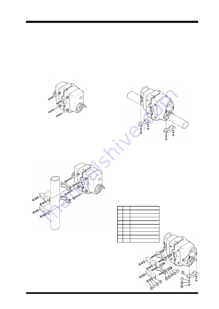
Mounting the Rotators Separately
Only do this if the elevation rotator is to be
mounted alone on the mast. You will need four
long stud bolts and four additional pipe clamps
(available from your dealer).
1.
Slip an 8 mm spring washer over the short-
thread end of each stud bolt (x4), and screw
the stud bolts firmly into holes in the side
of the elevation rotator.
2.
Slip an 8 mm flat washer over each in-
stalled stud bolt, and then the pipe clamps.
Place another flat washer and then a spring
washer over the end of each stud bolt, and
start a nut on each to hold the hardware in
place.
Installing the boom in the Elevation Rotator.
Do these steps for all installations.
1.
Slide the boom through the rotator.
2.
Place one U-bolt over each arm of the ro-
tator, and assemble one pipe clamp, flat
washers, spring washers and nuts on the
U-bolts. Center the boom carefully, and
alternately tighten the nuts on each U-bolt
½-turn beyond the point where the spring
washers are flattened.
Be sure to leave enough slack in both the el-
evation control cable and the coaxial cable
feedline around the azimuth rotator so the an-
tenna can rotate 450° without straining the cable
or feedline.
For dual parallel arrays, feedlines should be
taped to the boom on either side of the rotator,
with enough slack left to allow 180° rotation
without stressing the feedlines.
Summary of Contents for G-5500DC
Page 2: ......
Page 11: ...G 5500 Schematic Diagram...


