background image

-1-

S

TATION

 M

ONITOR

SM-5000

O

PERATING

 M

ANUAL

I

NSTALLATION

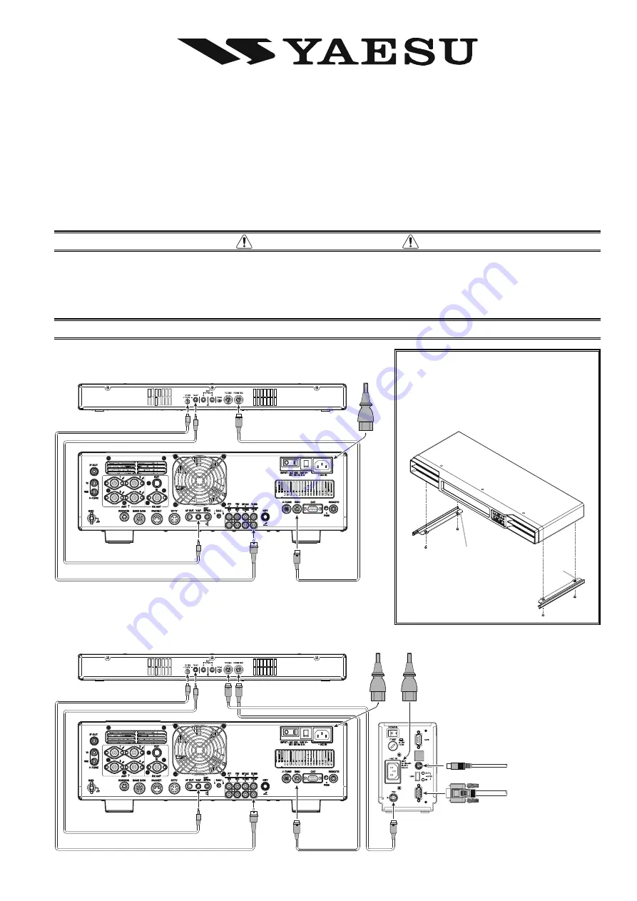
Before installing the SM-5000, turn off the Main Power Switch on the
rear panel of the FT

DX

5000.

SM-5000

FT

DX

5000

SM-5000

FT

DX

5000

DMU-2000

Thank you for your purchase. The 

SM-5000

 Station Monitor provides a visual display of the VFO-A band spectrum. Both strong

and weak signals are clearly depicted. The integrated stereo speakers provide comfortable receiver audio.

 S

AFETY

 I

NFORMATION


Do not modify this equipment.

Do not place this equipment in a location exposed to dust and/or high humidity.

Do not expose the 

SM-5000

 Station Monitor to direct sunlight or excessive temperatures.

D

M

U

~A

C

 IN

+1

3.

8V

V-

A

F

V-

A

F

+1

3.

8V

FR

O

M

 T

R

X

V-AF Cable  supplied with SM-5000

(

)

Mini-DIN Cable  supplied with SM-5000

(

)

DC POWER Cable  supplied with SM-5000

(

)

D

M

U

TR

X

KEYBOARD

MONITOR

~A

C

 IN

~A

C

 IN

+1

3.

8V

V-

A

F

V-

A

F

+1

3.

8V

TO

 D

M

U

FR

O

M

 T

R

X

V-AF Cable  supplied with SM-5000

(

)

Mini-DIN Cable  supplied with SM-5000

(

)

Mini-DIN Cable  supplied with DMU-2000

(

)

DC POWER Cable  supplied with SM-5000

(

)

S

IDE

 P

LATE

 I

NSTALLATION

If the 

SM-5000

 will be placed on top of

the 

FT

DX

5000

, attach the supplied Side

Plates on both sides of the 

SM-5000

 with

the supplied screws.

L

” mark (Bottom side)

R

” mark (Bottom side)

Note the left and right orienta-
tion of the Side Plates and in-
stall them correctly.

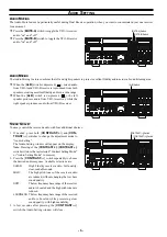
Summary of Contents for SM-5000

Page 1: ...dity Do not expose the SM 5000 Station Monitor to direct sunlight or excessive temperatures DMU AC IN 13 8V V AF V AF 13 8V FROM TRX V AF Cable supplied with SM 5000 Mini DIN Cable supplied with SM 5000 DC POWER Cable supplied with SM 5000 DMU TRX KEYBOARD MONITOR AC IN AC IN 13 8V V AF V AF 13 8V TO DMU FROM TRX V AF Cable supplied with SM 5000 Mini DIN Cable supplied with SM 5000 Mini DIN Cable ...

Page 2: ...nly VFO A or VFO B the audio is routed to both speakers regardless of the switch position MUTE A MUTE B Switches The MUTE A switch allows you to mute the audio from the VFO A receiver Similarly the MUTE B switch al lows you to mute the audio from the VFO B receiver This can be particularly useful during Dual Receive op eration when you want to concentrate on just one receiver for a moment REAR PAN...

Page 3: ...p name SCOPE while the SUB DISPLAY II window will show the Menu item The SUB DISPLAY III window shows the setting of the currently selected Menu item 2 Rotate the VFO A SELECT knob to select the Menu item MODE 3 Rotate the VFO B SELECT knob to select CENTER The current VFO A frequency is displayed at the center of the screen 4 Rotate the VFO A SELECT knob to select the Menu item SPAN then rotate t...

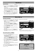
Page 4: ...Available selections are 25 kHz 50 kHz 100 kHz 250 kHz 500 kHz 1000 kHz and 2500 kHz 5 Rotate the VFO A SELECT knob to select the Menu item ATT then rotate the VFO B SELECT knob to select the display attenuation value according to current propaga tion conditions your operating frequency and antenna etc Available selections are 0 dB 10 dB and 20 dB 6 Press the C S key briefly to save the new settin...

Page 5: ...n the screen by a bold vertical line for ease of status recognition 4 Rotate the VFO A SELECT knob to select the Menu item SPAN then rotate the VFO B SELECT knob to select the desired frequency span to monitor Available selections are 25 kHz 50 kHz 100 kHz 250 kHz 500 kHz 1000 kHz and 2500 kHz 5 Rotate the VFO A SELECT knob to select the Menu item ATT then rotate the VFO B SELECT knob to select th...

Page 6: ...eived audio with four additional choices 1 If needed press both CONTRAST and CON TRAST switches to change the adjustment mode to Audio Setting The Audio Setting window will appear on the display Note Pressing of the CONTRAST CONTRAST switch will store the last selected Contrast Setting Mode or Audio Setting Mode to memory 2 Press the CONTRAST switch repeatedly to choose the desired audio response ...

Page 7: ...the display 3 Press the CONTRAST switch to reduce the contrast of the display 4 A few seconds after pressing the CONTRAST CONTRAST switch the Contrast window will close SPECTRUM SCOPE DISPLAY ON OFF You may turn off the Spectrum Scope Display 1 Press and hold the FTDX5000 C S key for 2 seconds to engage the Scope Menu mode The SUB DISPLAY Iwindow will show the Group name SCOPE while the SUB DISPLA...

Page 8: ...5 mm Left and right speakers are identical Maximum Audio Output 1 5 W 1 5 W 8 Ω Case Size WxHxD 18 x 1 8 x 7 1 462 x 45 x 181 mm Weight Approx 5 5 lbs 2 5 kg RESETTING THE MICROPROCESSOR Press and hold the CONTRAST and CONTRAST switches while turning the FTDX5000 transceiver on to reset the Sound Quality Phase Inversion and Contrast settings to their factory default VERTEX STANDARD CO LTD 4 8 8 Na...

Reviews: