background image

FCC ID: K66VX-3200V-2

Alignment

3/6

Vertex Standard Co., Ltd.

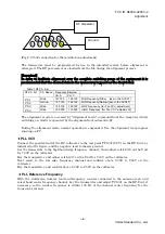
(Fig 2: J1502 connection for the modulation adjustment)

The transceiver must be programmed for use in the intended system before alignment is
attempted. The RF parameters are loaded from the file during the alignment process.

[Important]
In order to facilitate alignment over the complete switching range of the equipment it is
recommended that the channel data in the transceiver is preset as the chart below.

        Table.1 RF Ch. List

Frequency(Simplex)

RF Ch. list

Ch. Space

Ver. A

Ver. C

Ch 1

Wide

147.100

162.100

MID Frequency(Wide)


 [use in the  SVC47]

Ch 2

Narrow

147.100

162.100

MID Frequency(Narrow) [use in the SVC47 ]

Ch 3

Wide

134.100

148.100

LOW Frequency  [for PLL VCV  adjustment]

Ch 4

Wide

159.900

173.900

HIGH Frequency  [for PLL VCV  adjustment]

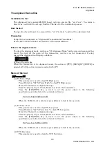
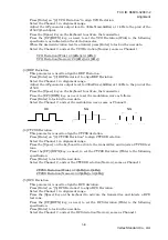
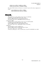
The alignment mode is accessed by “Alignment mode” command from the computer whilst
switching on. And it is operated by the alignment tool automatically.

During the alignment mode, normal operation is suspended. Use the alignment tool program
running on PC.

PLL VCV

Connect the positive lead of the DC voltmeter to the test point TP1007 (VCV) on the RF-Unit, as
indicated in the figure, and the negative lead to chassis ground.
Set the transceiver to the high band edge frequency channel, then adjust coil L1016 on the Unit
for 7.40V on the voltmeter.
Key the transmitter, and adjust coil L1017 on the Unit for 7.40V on the voltmeter.
Next select to the low edge frequency channel and confirm above 2.00V to 2.50V on the
voltmeter.
Key the transmitter, and confirm above 2.00V to 2.50V on the voltmeter.


PLL Reference Frequency

With the wattmeter, dummy load and frequency counter connected to the antenna jack, and
select band center frequency channel, key the transmitter and adjust TC1001 on the RF-Unit, if
necessary, so the counter frequency is within 100 Hz of the channel center frequency for the
transceiver version.

5

4

3

2

1

9

8

7

6

AF Generator

Ground

Summary of Contents for VX-3200V

Page 1: ... specifications after replacing any faulty components Those who do undertake any of the following alignments are cautioned to proceed at their own risk Problems caused by unauthorized attempts at realignment are not covered by the warranty policy Also Vertex Standard reserves the right to change circuits and alignment procedures in the interest of improved performance without notifying owners Unde...

Page 2: ...at the ambient temperature be the same as that of the transceiver and test equipment and that this temperature be held constant between 20 and 30 C 68 86 F When the transceiver is brought into the shop from hot or cold air it should be allowed time to come to room temperature before alignment Whenever possible alignments should be made with oscillator shields and circuit boards firmly affixed in p...

Page 3: ...whilst switching on And it is operated by the alignment tool automatically During the alignment mode normal operation is suspended Use the alignment tool program running on PC PLL VCV Connect the positive lead of the DC voltmeter to the test point TP1007 VCV on the RF Unit as indicated in the figure and the negative lead to chassis ground Set the transceiver to the high band edge frequency channel...

Page 4: ... action of PTT MON UP DOWN is ignored All of the action is remote controlled by PC Menu of the tool 0 Common TX 0 Tx Power High This parameter is used to align TX High power Press Enter on 0 Tx Power High to align TX High power Select the Channel 1 in alignment range Press the Space key on the keyboard to activate the transmitter Press the UP DWN key as need to set the power output to the followin...

Page 5: ...mitter Press the UP DWN key as need to set the modulation wave as follows Press Enter to lock in the new data Select the Channel 2 and set the modulation wave same as Channel 1 OK NG NG 4 CTCSS Deviation This parameter is used to align the CTCSS deviation Press Enter on 4 CTCSS Deviation to align CTCSS Deviation Select the Channel 1 in alignment range Press the Space on the keyboard to activate th...

Page 6: ... alignment RX Tuning after ending Select the MID frequency channel in alignment range Set the SG output level to 0dBµ EMF and obey the message 1 Threshold NSQL This parameter is used to align the noise level in squelch Threshold It adjusts this alignment RX Tuning after ending Select the MID frequency channel in alignment range Set the SG output level to 8dBµ EMF and obey the message 2 RX Tune Thi...

Reviews: