background image

VX-6E O

PERATING

 M

ANUAL

91

S

ET


(

M

ENU

)

 M

ODE

S

ET

 M

ODE

 I

TEM

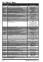
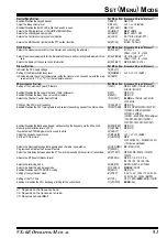
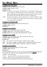
7 [BEEP]
9 [BP LVL]
11 [BSY.LED]
28 [HM/RV]
33 [LAMP]
35 [LOCK]

36 [M/T-CL]

S

ET

 M

ODE

 I

TEM

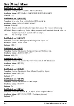
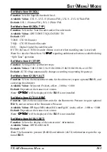
62 [SU1.ALT]

63 [SU1.BRM]

64 [SU1.SET]

S

ET

 M

ODE

 I

TEM

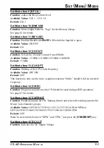
16 [DC VLT]
19 [DIMMER]
65 [TEMP]

S

ET

 M

ODE

 I

TEM

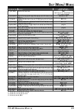
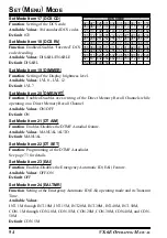
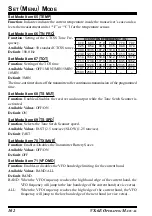
1 [APO]

5 [ATT]
6 [BCLO]
12 [CH CNT]

13 [CLK.SFT]
15 [CWTRNG]

25 [EDG.BEP]
27 [HLF.DEV]
34 [LED LT]
37 [MCGAIN]
41 [ON TMR]

42 [OPN.MSG]
47 [PSWD]
48 [PTT.DLY]

50 [RF SQL]

52 [RX MD]
54 [S SRCH]
58 [SPLIT]
61 [STEP]

67 [TOT]
71 [VFO MD]

A

VAILABLE

 V

ALUES


(

D

EFAULT

)

ON

 / OFF

LVL 1 - LVL 9 (

LVL 5

)

ON

 / OFF

REV

 / HOME

KEY

 / CONT / OFF

KEY / DIAL / 

K+D

 / PTT /

P+K / P+D / ALL
MONI / T-CALL

Ú

2

A

VAILABLE

 V

ALUES


(

D

EFAULT

)

M / Ft

Ú

2, 3

Offset: –1000 - 

0

 - +1000

HP / MB / HG / IC

Ú

2, 3

Offset: –1000 - 

0

 - +1000

OFF

 / BARO / ALTI

Ú

3

A

VAILABLE

 V

ALUES


(

D

EFAULT

)

--
LVL 0 - LVL 12 (

LVL 7

)

--

A

VAILABLE

 V

ALUES


(

D

EFAULT

)

OFF

 / 30MIN / 1HOUR / 3HOUR /

5HOUR / 8HOUR

OFF

 / ON

OFF

 / ON

±5 MHz

 / ±10 MHz / ±50 MHz /

±100 MHz

OFF

 / ON

OFF

 / 4WPM-13WPM / 15WPM /

17WPM / 20WPM / 24WPM /
30WPM / 40WPM
(20CPM - 65CPM (5CPM multiples)
/ 75CPM / 85CPM /100CPM /
120CPM / 150CPM / 200CPM)

OFF

 / ON

OFF

 / ON

---
LVL 1 - LVL 10 (

LVL 5

)

OFF

 /

00H10M (00:10) - 24H00M (24:00)
(10 minutes multiples)

DC

 / MSG / OFF

--

OFF

 / 20MS / 50MS / 100MS /

200MS

OFF

 / S1 / S2 / S3 / S4 /

S5 / S6 / S7 / S8 / S9 / S9+

AUTO

 / N-FM / AM / W-FM

SINGLE

 / CONT

OFF

 / ON

5.0k / 10.0k / 12.5k / 15.0k / 20.0k /
25.0k / 50.0k / 100.0k / 

AUTO

OFF / 1MIN / 

3MIN

 / 5MIN / 10MIN

BAND

 / ALL

S

WITCH

/K

NOB

 S

ETTING

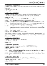
Enables/Disables the keypad beeper.
Adjust the Beep volume level.
Enables/Disables the BUSY LED while the Squelch is open.
Selects the Primary function of the [HM/RV(EMG)R/H] key.
Selects the LCD/Keypad Lamp mode.
Selects the Control Locking lockout combination.

Selects the MONI switch (just below the PTT switch) function.

SU-1 S

ETTING

Selects the measurement units for the altimeter, and correcting the altimeter.

Selects the measurement units for the Barometric Pressure, and correcting the Barometric Pres-

sure.

Selects the display of the sensor units’ information.

D

ISPLAY

 S

ETTING

Indicates the DC Supply Voltage
Setting of the Display brightness level.
Indicates indicate the current temperature inside the transceivre’s case and selects the mea-

surement units (“°F” or “°C”) for the temperature sensor.

M

ISCELLANEOUS

 S

ETTING

Setting of the Automatic Power-Off feature.

Enables/Disables the Receiver Front-end (10 dB) Attenuator.
Enables/Disables the Busy Channel Lock-Out feature.
Selects the Channel Counter Search Width.

Shifting of the CPU clock frequency.
Enables/Disables the CW Training feature and selects the sending speed of the Morse Code.

Enables/Disables the Band-edge beeper while selecting the frequency via the DIAL knob.
Reducing the Deviation level by 50 %.
Illuminates the STROBE glows continuously in white.
Adjust the microphone gain level.
Set the ON Timer time.

Selects the Opening Message that appears when the radio is powered on.
Programs and activates the Password feature.
Select the time delay between when the PTT switch is pressed and the carrier is transmitted.

Adjusts the RF Squelch threshold level.

Selects the receiving mode.
Selects the Smart Search Sweep mode.
Enables/Disables split CTCSS/DCS coding.
Setting of the synthesizer steps.

Setting of the TOT time
Enables or disables the VFO band edge limiting for the current band.

Ú

1: Depends on the frequency band.

Ú

2: Depends on the transceiver version.

Ú

3: Requires optional 

SU-1

.

Summary of Contents for VX-6E

Page 1: ...apan VERTEX STANDARD US Headquarters 10900 Walker Street Cypress CA 90630 U S A YAESU EUROPE B V P O Box 75525 1118 ZN Schiphol The Netherlands YAESU UK LTD Unit 12 Sun Valley Business Park Winnall Close Winchester Hampshire SO23 0LB U K VERTEX STANDARD HK LTD Unit 5 20 F Seaview Centre 139 141 Hoi Bun Road Kwun Tong Kowloon Hong Kong ...

Page 2: ...LO 82 Transmitter Time Out Timer TOT 83 Changing the TX Deviation Level 83 Reset Procedures 85 Cloning 86 Set Menu Mode 87 Specifications 104 AUTO Mode Preset Operating Parameters 106 General Description 1 Accessories Options 2 Controls Connections 3 Top Front Panel 3 LCD 4 Side Bottom Panel 5 Keypad 6 Installation of Accessories 8 Antenna Installation 8 Belt Clip Hand Strap Installation 8 Install...

Page 3: ...and a security Password feature that will allow you to turn on and operate your transceiver only after you enter your Password Additional features include a convenient access key for Vertex Standard s WIRES Wide coverage Internet Repeater Enhancement System a trans mit Time Out Timer TOT Automatic Power Off APO Automatic Repeater Shift ARS Yaesu s exclusive ARTS Auto Range Tran sponder System whic...

Page 4: ...ter CN 3 BNC to SMA Adapter SU 1 Barometric Pressure Sensor Unit CSC 91 Soft Case Ú B suffix is for use with 100 120 VAC C suffix is for use with 230 240 VAC and U suffix is for use with 230 VAC Availability of accessories may vary Some accessories are supplied as standard per local requirements while others may be unavailable in some regions This product is designed to perform optimally when used...

Page 5: ...tal Display The display shows current operating conditions as indicated on the next page h POWER Switch Press and hold in this switch for one second to toggle the transceiver s power on and off i Keypad These 18 keys select many of most im portant operating features on the VX 6E The functions of the keys are described in detail on the pages to follow j Microphone The internal microphone is located...

Page 6: ...ature Active Battery Saver Active Battery Indicator Low TX Power Selected Bell Alarm Active Automatic Power Off Active Dual Watch Active Operating Frequency Memory Channel Number Skip Memory Channel or Preferential Memory Channel Repeater Shift Direction CTCSS DSC Operation Internet Connection Feature Active Priority Channel DMR Channel Recall ...

Page 7: ...e T CALL 1750 Hz for repeater access e EXT DC Jack This coaxial DC jack allows con nection to an external DC power source 6 16V DC The center pin of this jack is the Positive con nection Do not allow the VX 6E to become submerged in water while the rubber cap over the EXT DC jack is removed f Battery Pack Latch Open this latch for battery removal CONTROL CONNECTIONS SIDE BOTTOM PANEL c d e f ...

Page 8: ...and Stores the current setting into Direct Memory Recall Channel 1 Frequency entry digit 8 Frequency entry digit 7 Selects the synthesizer steps to be used during VFO operation Activates the ARTSTM feature Activates the EAITM Emergency Automatic ID feature Selects the desired transmit power output level Activates the Key Lockout feature Reverses the transmit and receive frequencies while working t...

Page 9: ... the DTMF mode Engage the Special Search mode Switches frequency control between the VFO and Memory Systems Activates the Priority Dual Watch function Engages the Set Menu Mode Enter the Special Bank mode Activates the Second ary key function Disables the Second ary key function Activates the Memory Write mode for memory channel storage Activates the Memory Tune mode while in the Memory Recall mod...

Page 10: ...nce at all frequencies To install the supplied antenna hold the bottom end of the an tenna then screw it onto the mating connector on the transceiver until it is snug Do not over tighten by use of extreme force Notes Never transmit without having an antenna connected When installing the supplied antenna never hold the up per part of the antenna while screwing it onto the mating connector on the tr...

Page 11: ...Ion pack could occur if a cell or cells become acci dentally short circuited 2 Danger of explosion if battery is incorrectly replaced Replace only with the same or equivalent type CAUTION Danger of explosion if battery is incorrectly replaced Replace only with the same or equivalent type BATTERY CHARGING If the battery has never been used or its charge is depleted it may be charged by connect ing ...

Page 12: ...Pack Latch on the bottom of the radio The FBA 23 does not provide connections for charging since Alkaline cells cannot be re charged Therefore the NC 72 E DC 5B or E DC 6 may safely be connected to the EXT DC jack when the FBA 23 is installed 1 The FBA 23 is designed for use only with AA type Alkaline cells 2 If you do not use the VX 6E for a long time remove the Alkaline batteries from the FBA 23...

Page 13: ...a Set Mode Item 37 MCGAIN MCGAIN MCGAIN MCGAIN MCGAIN see page 18 for details Be sure to turn the transceiver and TNC off before connecting the cables so as to prevent voltage spikes from possibly damaging your transceiver When you are operating on Packet switch the Receive Battery Saver OFF as the sleep cycle may collide with the beginning of an incoming Packet transmission causing your TNC not t...

Page 14: ...y voltage will indi cated on the display for 2 seconds if you are using the FNB 80LI Battery Pack the small Lit notation at the top of the display confirms that the Lithium Ion Battery Pack has been detected After this 2 second interval the display will resume its nor mal indication of the operating frequency 3 To turn the VX 6E off press and hold in the POWER switch again for one second 1 If you ...

Page 15: ... 2 2 2 2 for FM and AM and 2 2 2 2 2 or 3 3 3 3 3 for Wide FM this is point of maximum sensitivity to weak signals 4 When you are satisfied with the Squelch threshold setting press the PTT key momen tarily to save the new setting and exit to normal operation 1 A special RF Squelch feature is provided on the VX 6E This feature allows you to set the squelch so that only signals exceeding a certain S...

Page 16: ...recom mend that you connect an external antenna for improved reception FREQUENCY NAVIGATION The VX 6E will initially be operating in the VFO mode a channelized system which allows free tuning throughout the currently selected operating band Three basic frequency navigation methods are available on the VX 6E 1 Tuning Dial Rotation of the DIAL allows tuning in the pre programmed steps established fo...

Page 17: ...o begin scanning toward a higher frequency The scan ner will stop when it receives a signal strong enough to break through the Squelch threshold The VX 6E will then hold on that frequency according to the setting of the RESUME mode Set Mode Item 48 RESUME RESUME RESUME RESUME RESUME See page 46 for details regarding Scan Operation If you wish to reverse the direction of the scan i e toward a lower...

Page 18: ...firms High Power operation while deflection of three bars indicates Low 1 Power operation Five bars indi cates Low 2 Power operation and seven bars indicates Low 3 Power operation Additionally the LOW icon will appear at the bottom of the display while operating on the Low Power settings 1 If you re just talking to friends in the immediate area you ll get much longer battery life by switching to L...

Page 19: ...W2 or LOW3 LOW3 LOW3 LOW3 LOW3 to appear 3 Press the F W key followed by the LK TXPO key repeatedly if necessary to make the HIGH HIGH HIGH HIGH HIGH notation appear and restore High Power operation 1 The VX 6E is smart You can set up Low power on the 144 MHz band while leaving 430 MHz on High power and the radio will remember the different settings on both bands And when you store memories you ca...

Page 20: ...ou have made your selection press and hold in the 0 SET key for 2 sec onds to save the new setting and exit to normal operation AM BROADCAST RECEPTION The VX 6E includes provision for reception of AM broadcasts either on the standard medium wave MW broadcast band or on the shortwave bands up to 30 MHz 1 Press the BAND SCN BND DN key or press the F W key followed by the BAND SCN BND DN key repetiti...

Page 21: ...or reception in the FM broadcast band utilizing a wide bandwidth filter which provides excellent fidelity To Activate FM Broadcast Reception 1 Press the BAND SCN BND DN key or press the F W key followed by the BAND SCN BND DN key repetitively un til a frequency in the FM broadcast band appears on the display The total frequency range included in the FM band is 88 108 MHz 2 Rotate the DIAL to selec...

Page 22: ...ble K P K P K P K P K P Both the keypad and PTT switch are locked out D P D P D P D P D P Both the DIAL and PTT switch are locked out ALL ALL ALL ALL ALL All of the above are locked out To lock out some or all of the keys 1 Press the F W key then press the 0 SET key to enter the Set mode 2 Rotate the DIAL knob to select Set Mode Item 35 LOCK LOCK LOCK LOCK LOCK 3 Press the 0 SET key momentarily to...

Page 23: ...e the setting to OFF OFF OFF OFF OFF 5 Press the PTT switch to save the new setting and return to nor mal operation 6 To turn the beep back on again select ON ON ON ON ON in step 4 above KEYPAD LCD ILLUMINATION Your VX 6E includes a reddish illumination lamp which aids in nighttime operation The reddish illumination yields clear viewing of the display in a dark environment with mini mal degradatio...

Page 24: ...disabled 3 5 kHz and 15 kHz steps are not available for use on 250 300 MHz nor above 580 MHz CHANGING THE RECEIVING MODE The VX 6E provides for automatic receiving mode chang ing when the radio is tuned to different operating frequen cies However should an unusual receiving situation arise in which you need to change other receiving mode just press the MODE SP S SQ TYP key The receiving modes avai...

Page 25: ...he squelch threshold S1 S1 S1 S1 S1 S2 S2 S2 S2 S2 S3 S3 S3 S3 S3 S4 S4 S4 S4 S4 S5 S5 S5 S5 S5 S6 S6 S6 S6 S6 S7 S7 S7 S7 S7 S8 S8 S8 S8 S8 S9 S9 S9 S9 S9 S9 S9 S9 S9 S9 or OFF OFF OFF OFF OFF 5 Press the PTT switch to save the new setting and return to normal operation CHECKING THE BATTERY VOLTAGE The VX 6E s microprocessor includes programming which will measure the current bat tery voltage 1 P...

Page 26: ...icons will appear at the top of the LCD when repeater shifts have been enabled AUTOMATIC REPEATER SHIFT ARS The VX 6E provides a convenient Automatic Repeater Shift feature which causes the appropriate repeater shift to be applied automatically whenever you tune into the desig nated repeater sub bands in your country These sub bands are shown below If the ARS feature does not appear to be working ...

Page 27: ...ur manual setting of the shift direction Turn ARS off if you do not wish this to happen Changing the Default Repeater Shifts If you travel to a different region you may need to change the default repeater shift so as to ensure compatibility with local operating requirements To do this follow the procedure below 1 Set the VX 6E s frequency to the band on which you wish to change the default repeate...

Page 28: ...MG R H key again to cause operation to revert to normal monitoring of the re peater downlink output frequency While you are listen ing on the input frequency to the repeater using the HM RV EMG R H key the repeater offset icon will blink The configuration of this key may be set either to RV for checking the input frequency of a repeater or HM for instant switching to the Home channel for the band ...

Page 29: ...This can help keep your radio quiet until a specific call is received which may be helpful while operating in congested areas of the band 1 You may notice a RV TN RV TN RV TN RV TN RV TN indication on the display while you rotate the DIAL knob in this step this means that the Reverse Tone Squelch system is active which mutes your VX 6E s receiver instead of opening the squelch when it receives a c...

Page 30: ...our friend s use transceivers equipped with this advanced feature Just as in CTCSS operation DCS requires that you set the Tone Mode to DCS and that you select a tone code 1 Press the F W key then press the MODE SP S SQ TYP key to enable selection of the CTCSS DCS mode 2 Rotate the DIAL knob until the DCS DCS DCS DCS DCS indication appears on the display this activates the DCS Encoder Decoder 3 Pr...

Page 31: ...of an external linear amplifier Note that code inversion does not mean that any of the above listed equipment is defec tive In certain amplifier configurations the output signal phase is inverted from the input Small signal or power amplifiers having an odd number 1 3 5 etc of amplification stages may result in inversion of a transmitted or received DCS code While under most circumstances this sho...

Page 32: ... Item 8 BELL BELL BELL BELL BELL 5 Press the 0 SET key momentarily to enable adjustment of this Set Mode Item 6 Rotate the DIAL knob to set the desired number of rings of the Bell The available choices are 1 1 1 1 1 3 3 3 3 3 5 5 5 5 5 or 8 8 8 8 8 rings CONT CONT CONT CONT CONT continuous ringing or OFF OFF OFF OFF OFF 7 Press the PTT switch momentarily to save the new setting and exit to normal ...

Page 33: ...splay 2 Press the F W key then press the 2 CODE key 3 Press and hold in the BAND SCN BND DN key for one sec ond to start scanning for the incoming CTCSS or DCS tone code 4 When the radio detects the correct tone or code it will halt on that tone code and audio will be allowed to pass Press the BAND SCN BND DN key to lock in that tone code then press the F W key to exit to normal operation If the T...

Page 34: ...de and Decodes a CTCSS Tone the icon will appear and the icon will blink during op eration Select the desired operating mode from the selections shown above TONE CALLING 1750 HZ If the repeaters in your country require a 1750 Hz burst tone for access typically in Eu rope you can set the MONI switch to serve as a Tone Call switch instead To change the configuration of this switch we again use the S...

Page 35: ...Bank can be assigned up to 100 channels from the standard and PMS memory channels Special Memory Channels which include A Emergency Automatic ID EAI Channel 10 Direct Memory Recall Channels 10 Weather Broadcast Channels 89 Popular Short wave Broadcast Station Memory Channels 281 VHF Marine Channels Action Band 2 UHF TV Band 430 MHz Band Action Band 1 VHF TV Band 144 MHz Band Air Band FM BC Band 50...

Page 36: ...nnel selection feature to select the next highest memory channel above the last stored memory channel by instead of the next available free channel via the Set Mode Item 38 MW MD see page 97 2 In step 4 above you may jump 100 memory channels if you re in a hurry 101 Æ 201 Æ 301 by pressing the P DMR key multiple times if necessary Similarly if you wish to store to the designated memory channel an ...

Page 37: ...mbers Memory Channel 000 1000 Programmable Memory channels L1 1001 U1 1002 L50 1099 and U50 1100 In these case you do not need to press the V M DW MT key LABELING MEMORIES You may wish to append an alpha numeric Tag label to a memory or memories to aid in recollection of the channel s use such as a club name etc This is easily accomplished using the Set Mode 1 Recall the memory channel on which yo...

Page 38: ... to enable adjustment of this Item s setting 5 Rotate the DIAL knob to set this Set Mode Item to ALPHA ALPHA ALPHA ALPHA ALPHA thus enabling the alpha numeric display 6 Press the PTT key to save the new setting and activate the al pha numeric Tag To disable the alpha numeric Tag enabling the frequency display just repeat the above procedure rotating the DIAL knob to select FREQ FREQ FREQ FREQ FREQ...

Page 39: ...or VFO operation on the current band will be the steps used during Memory Tuning 4 If you wish to return to the original memory frequency just press the V M DW MT key momentarily The display will revert to display of the alpha numeric Tag if any that may have originally appeared on the LCD 5 If you wish to store a new frequency set during Memory Tuning just press and hold in the F W key for one se...

Page 40: ... mode 2 Press and hold in the F W key for one second then rotate the DIAL knob to select the memory channel to be Masked 3 Press the LK TXPO key momentarily The display will revert to memory chan nel 1 The previously selected memory will be Masked 4 To Unmask the hidden memory repeat the above procedure press and hold in the F W key for one second rotate the DIAL to select the masked memory s numb...

Page 41: ...in the F W key for one second 4 While the memory channel number is blinking just press the HM RV EMG R H key The frequency and other data if any will now be stored in the special HOME channel register 5 You may repeat this process on the other operating bands 6 To r e c a l l t h e H O M E c h a n n e l p r e s s t h e HM RV EMG R H key momentarily while operating either in the VFO or MR mode The ...

Page 42: ...he PMS memory channels L1 U1 through L50 U50 may not be as signed to a Memory Bank Memory Bank Recall 1 Press the V M DW MT key if needed to enter the Memory mode 2 Press the BAND SCN BND DN key to activate the Memory Bank mode The Memory Bank number will appear on the dis play 3 Press the F W key followed by the BAND SCN BND DN key then rotate the DIAL knob to select the desired Memory Bank BANK ...

Page 43: ...the F W key then press the 0 SET key to enter the Set mode 2 Rotate the DIAL knob to select Set Mode Item 10 BNK NM BNK NM BNK NM BNK NM BNK NM 3 Press the 0 SET key momentarily then rotate the DIAL knob to recall the memory bank on which you wish to change a label 4 Press the MODE SP S SQ TYP key to enable changing of the name tag 5 Rotate the DIAL knob to select the first digit of the desired la...

Page 44: ... repeating the above process Recalling the Direct Memory Recall Channels 1 Press and hold in the P DMR key for 2 seconds to recall the Direct Memory Recall Channel mode The icon will ap pear at the upper left corner of the display while operating on a Direct Memory Recall Channel 2 Press the numeric 0 through 9 key correspond ing to the Direct Memory Recall Channel you wish to recall 3 Once you ha...

Page 45: ...e Deutsche Welle Deutsche Welle Italian Radio International Italian Radio International Italian Radio International Italian Radio International Swiss Radio International Swiss Radio International Swiss Radio International Swiss Radio International Radio Vlaanderen International Radio Vlaanderen International Radio Vlaanderen International Radio Vlaanderen International Radio Nederland Radio Nederl...

Page 46: ...CH WX CH WX CH WX CH thus recalling the Weather Broadcast Memory Bank 3 Rotate the DIAL knob to select the desired Weather Broadcast channel 4 If you wish to scan this bank to search for louder stations just press the PTT switch When the scanner pauses on a station press the PTT key once to halt the scan press it once moore to restart the scan 5 To exit to normal operation press the V M DW MT key ...

Page 47: ...25 159 750 159 775 159 800 159 825 159 850 159 875 159 900 159 925 159 950 159 975 160 000 160 025 160 050 160 075 CH No 164 165 166 167 168 169 170 171 172 173 174 175 176 177 178 179 180 181 182 183 184 185 186 187 188 189 190 191 192 193 194 195 196 197 198 199 200 201 202 203 204 Frequency MHz 160 100 160 125 160 150 160 175 160 200 160 225 160 250 160 275 160 300 160 325 160 350 160 375 160 4...

Page 48: ...e stations are still active BUSY BUSY BUSY BUSY BUSY In this mode the scanner will halt on a signal it encounters One second after the carrier has dropped because the other station s ceased transmission the scanner will resume In the case of con stant carrier signals like Weather Station broadcasts the scanner will likely remain on this frequency indefinitely HOLD HOLD HOLD HOLD HOLD In this mode ...

Page 49: ...and 3 Release the BAND SCN BND DN key to start scanning 4 If and when the scanner encounters a signal strong enough to open the squelch the scanner will halt temporarily the decimal point of the frequency display will blink during this Pause condition 5 The scanner will then resume according to the Scan Resume mode selected in the previous section 6 To cancel scanning press the PTT switch or V M D...

Page 50: ...cy during VFO scanning 1 While VFO scanning is stopped pause state on the frequency that you do not need press and hold in the F W key for one second then rotate the DIAL knob to select the desired Frequency Skip Memory channel 901 901 901 901 901 999 999 999 999 999 The microproces sor will automatically select the next available free Frequency Skip Memory chan nel a memory register on which no d...

Page 51: ...el the alpha numeric Tag will appear while you are select ing the Memory Scan mode 3 Release the BAND SCN BND DN key to initiate scanning 4 As with VFO scanning the scanner will halt on any signal encountered that is strong enough to open the squelch it will then resume scanning according to the Scan Re sume mode set previously When there are no memory channels corresponding to the selected Memory...

Page 52: ...en you have selected them one by one for the Preferential Scan List Here is the procedure for setting up and using the Preferential Scan List 1 Recall the Memory Channel which you wish to add to the Preferential Scan List 2 Press the F W key then press the 0 SET key to enter the Set mode 3 Rotate the DIAL knob to select Set Mode Item 57 SKIP SKIP SKIP SKIP SKIP 4 Press the 0 SET key momentarily to...

Page 53: ...e a blinking X icon appended to the channel number will be scanned Memory Bank Scan When the Memory Bank feature is engaged the scanner sweeps only memory channels in the current Memory Bank However if the Memory Bank Link Scan feature is enabled you may sweep the memory channels in several Memory Banks which you have selected To enable the Memory Bank Link Scan feature 1 Set the radio to the Memo...

Page 54: ...hold in the BAND SCN BND DN key for one sec ond and while holding the BAND SCN BND DN key in rotate the DIAL knob to select the desired PMS frequency pair PMSxx PMSxx PMSxx PMSxx PMSxx then release the BAND SCN BND DN key 5 Releasing the BAND SCN BND DN key to initiates the Pro grammable Band Limit Memory Scan the Memory Channel number will be replaced by Pxx Pxx Pxx Pxx Pxx Scanning and tuning wi...

Page 55: ...a Memory Bank you must exit from Memory Bank operation by pressing the BAND SCN BND DN key momentarily 2 Press and hold in the F W key for one second then rotate the DIAL knob to select the memory channel you wish to be the Priority channel 3 Press the BAND SCN BND DN key The icon will appear to the left side of the memory channel number indicat ing it is the Priority channel while recalling the c...

Page 56: ...this Set Mode Item to OFF OFF OFF OFF OFF 5 When you have made your selection press the PTT key to save the setting and exit to normal operation BAND EDGE BEEPER The VX 6E will automatically beep when a band edge is encountered during scanning either in standard VFO scanning or during PMS operation You may also enable this feature band edge beeper to sound the beeper when the frequency reaches the...

Page 57: ... 1 Press the F W key then press the 0 SET key to enter the Set mode 2 Rotate the DIAL knob to select Set Mode Item 73 WX ALT WX ALT WX ALT WX ALT WX ALT 3 Press the 0 SET key momentarily to enable adjustment of this Set Mode Item 4 Rotate the DIAL knob so as to select ON ON ON ON ON 5 When you have made your selection press the PTT key to save the setting and exit to normal operation 6 To disable ...

Page 58: ...arch Mode 1 Press the F W key then press the 0 SET key to enter the Set mode 2 Rotate the DIAL knob to select Set Mode Item 54 S SRCH S SRCH S SRCH S SRCH S SRCH 3 Press the 0 SET key momentarily to enable adjustment of this Set Mode Item 4 Rotate the DIAL knob to select the desired Smart Search mode see above 5 When you have made your selection press the PTT switch to save the setting and exit to...

Page 59: ... to normal operation press the MODE SP S SQ TYP key Smart Search is a great tool when visiting a city for the first time You don t need to spend hours looking up repeater frequencies from a reference guide book just ask your VX 6E where the action is SMART SEARCH OPERATION ...

Page 60: ... Set the radio to the VFO mode in the predicted frequency range for the transmitter to be measured 2 Bring the VX 6E into close proximity to the transmitter to be measured 3 Press and hold in the MODE SP S SQ TYP key for one second and rotate the DIAL knob while holding in the MODE SP S SQ TYP key to that CH CNT CH CNT CH CNT CH CNT CH CNT indication appears on the display this acti vates the Chan...

Page 61: ...unter Bandwidth 1 Press the F W key then press the 0 SET key to enter the Set mode 2 Rotate the DIAL knob to select Set Mode Item 12 CH CNT CH CNT CH CNT CH CNT CH CNT 3 Press the F W key momentarily to enable adjustment of this Set Mode Item 4 Rotate the DIAL knob to select the desired bandwidth 5 When you have made your selection press the PTT key to save the setting and exit to normal operation...

Page 62: ...Storing the CTCSS Tone Pairs for EPCS Operation 1 Press the F W key then press the 0 SET key to enter the Set mode 2 Rotate the DIAL knob to select Set Mode Item 45 PAG CDR PAG CDR PAG CDR PAG CDR PAG CDR for the Receiving CTCSS Tone Pair or Set Mode Item 46 PAG CDT PAG CDT PAG CDT PAG CDT PAG CDT for the Transmitting CTCSS Tone Pair 3 Press the 0 SET key momentarily to enable adjustment of this S...

Page 63: ... the fact that a call is coming in as described previously See page 30 for details Paging Answer Back When you press the PTT switch to respond to a page call the VX 6E transmits the same CTCSS tone pair This tone pair will open the Code Squelch of the calling station If you prefer you can have the VX 6E respond to page calls automatically transpond To enable this feature 1 Press the F W key then p...

Page 64: ...transmit the alarm tone except in a true emergency 2 The Emergency feature may be changed to another function via Set Mode Item 26 EMG S see page 95 for details EMERGENCY AUTOMATIC ID EAI FEATURE The Emergency Automatic ID EAI feature can be used for searching for persons who are incapacitated in disasters like earthquakes especially search and rescue personnel who may have become injured in a deb...

Page 65: ...inutes The callsign or name will be transmitted every 10 minutes The Emergency Automatic ID EAI Feature requires that you 1 store the CTCSS Tone Pair into the Receiving Pager Memory see page 60 for procedure and 2 store the desired UHF coordination frequency into Memory Channel EAI EAI EAI EAI EAI see page 34 for pro cedure Selecting the EAI mode and its Transmit Time 1 Press the F W key then pres...

Page 66: ...ODE key to enable adjustment of the Transmitting Pager Memory Set the CTCSS tone pair which is the same CTCSS tone pair stored in the Re ceiving Pager Code Memory of the missing person s radio A Rotate the DIAL knob to select the first tone B Press the BAND SCN BND DN key C Rotate the DIAL knob to select the second tone D Press the PTT switch to save the new setting and exit from setting mode 3 Pr...

Page 67: ... using it previ ously in non ARTS operation If you move out of range for more than one minute four pollings your radio will sense that no signal has been received three beeps will sound and the display will revert to OUTRNG OUTRNG OUTRNG OUTRNG OUTRNG If you move back into range your radio will again beep and the display will change back to the IN RNG IN RNG IN RNG IN RNG IN RNG indication During ...

Page 68: ...ws two kinds of alert beeps with the additional option of turning them off so as to alert you to the current status of ARTS operation Depending on your location and the potential annoyance associated with frequent beeps you may choose the Beep mode which best suits your needs The choices are INRANG INRANG INRANG INRANG INRANG The beeps are issued only when the radio first confirms that you are wit...

Page 69: ...s to clear any previous callsign 7 Rotate the DIAL knob to select the first letter number of your callsign then press the MODE SP S SQ TYP key momen tarily to save the first letter number and move on to the next character 8 Repeat the previous step as many times as necessary to complete your callsign Note that the slant bar is among the available characters should you be a portable station 9 If yo...

Page 70: ...ion To display the Sensor Information 1 Press the F W key then press the 0 SET key to enter the Set mode 2 Rotate the DIAL knob to select Set Mode Item 64 SU1 SET SU1 SET SU1 SET SU1 SET SU1 SET 3 Press the 0 SET key momentarily to enable adjustment of this Set Mode Item 4 Rotate the DIAL knob to select the sensor mode you wish to display BARO BARO BARO BARO BARO Indicates the Barometric Pressure ...

Page 71: ...s the F W key then press the 0 SET key to enter the Set mode 2 Rotate the DIAL knob to select Set Mode Item 62 SU1 ALT SU1 ALT SU1 ALT SU1 ALT SU1 ALT 3 Press the 0 SET key momentarily to enable adjustment of this Set Mode Item 4 Press the MODE SP S SQ TYP key to select the preferred units M M M M M or Ft Ft Ft Ft Ft 5 Press the F W key momentarily to enable correction of the Altimeter 6 Rotate th...

Page 72: ...B C C C C C D D D D D E E E E E F F F F F corresponding to the WIRES node to which you wish to establish an Internet link ask the node or re peater owner operator if you don t know the access number in the network Now press the PTT switch to exit from the selec tion mode 3 With the Internet Connection feature activated as in step 1 above the VX 6E will generate a brief 0 1 second DTMF tone accordi...

Page 73: ...he MODE SP S SQ TYP key momentarily to accept the first digit and move to the second digit of the DTMF string 9 Repeat the previous steps until you have completed the access code F 1101D 10 If you attach an alpha numeric name Tag to the Internet Memory proceed to the next step otherwise press and hold in the 0 SET key for one second to save the setting 11 Press the V M DW MT key momentarily to ena...

Page 74: ...n will appear in the upper right corner of the display 7 Rotate the DIAL knob while pressing the LK TXPO key to select the Internet Memory register number F 0 F 0 F 0 F 0 F 0 F63 F63 F63 F63 F63 corresponding to the Internet link repeater to which you wish to establish an Internet link then press the PTT switch momentarily to lock in the se lected access number 8 Once the Internet Connection featu...

Page 75: ...ving to send them manually Here is the DTMF Autodial storage procedure 1 Press the F W key then press the 0 SET key to enter the Set mode 2 Rotate the DIAL knob to select Set Mode Item 22 DT SET DT SET DT SET DT SET DT SET 3 Press the 0 SET key momentarily to enable adjustment of this Set Mode Item 4 Rotate the DIAL knob to select the DTMF Memory register into which you wish to store this DTMF str...

Page 76: ...lowed by the the 3 DTMF key then rotate the DIAL knob to select AUTO AUTO AUTO AUTO AUTO 2 Press the 3 DTMF key to save the new setting and exit to normal operation 3 While the DTMF Autodialer is activated first press the PTT switch then press the numerical key 1 through 9 corresponding to the DTMF memory string you wish to send Once the string begins you may release the PTT switch as the transmit...

Page 77: ...ctors Mixed Anr Anr Anr Anr Anr Send Alphabet Numeric and charactors Mixed Continuously in group of five 5 Rotate the DIAL knob to select the Morse speed You may select the units of the code speed between WPM Words per minute and CPM characters per minute by pressing the V M DW MT key 6 Press the BAND SCN BND DN key to switch the flashing of the LED white on and off a dot by the CW speed indicates...

Page 78: ...er letter 0 0 0 0 0 9 9 9 9 9 A A A A A B B B B B C C C C C D D D D D E E E E E substitute for and F F F F F substi tute for 6 Press the MODE SP S SQ TYP key to move to the next digit 7 Repeat steps 5 and 6 to program the remaining numbers letters of the desired password 8 If you make a mistake press the BAND SCN BND DN key to move back to the previous digit then re select the correct number lette...

Page 79: ...is talking on the channel the VX 6E will remain in the active mode then resume its sleep cycles This feature significantly reduces quiescent battery drain and you may change the amount of sleep time between activity checks using the Set Mode 1 Press the F W key then press the 0 SET key to enter the Set mode 2 Rotate the DIAL knob to select Set Mode Item 53 RXSAVE RXSAVE RXSAVE RXSAVE RXSAVE 3 Pres...

Page 80: ...ch the radio will turn itself on fully If the EAI feature is activated when the radio was turned off the radio also checks on the EAI frequency Memory Channel EAI EAI EAI EAI EAI for activity EAI EAI EAI EAI EAI Checks the EAI frequency Memory Channel EAI EAI EAI EAI EAI every 5 seconds If a properly coded signal is received on the EAI frequency the radio will turn itself on and then automatically...

Page 81: ...e Item to ON ON ON ON ON thus activating the Transmit Battery Saver 5 When you have made your selection press the PTT switch to save the new setting and exit to normal operation ATT FRONT END ATTENUATOR The attenuator will reduce all signals and noise by 10 dB and it may be used to make reception more pleasant under extremely crowded conditions 1 Press the F W key then press the 0 SET key to enter...

Page 82: ...e helps conserve battery life by automatically turning the radio off after a user defined period of time within which there has been no dial or key activity The avail able selections for the time before power off are 0 5 1 3 5 8 hours as well as APO Off The default condition for the APO is OFF and here is the procedure for activating it 1 Press the F W key then press the 0 SET key to enter the Set...

Page 83: ...e that this is not the time of day when the radio will turn on it is the numbaer of hours and minutes until the radio turns on 5 When you have made your selection press the PTT switch to save the new setting and exit to normal operation When the radio is turned off this activates the Automatic Power On feature a count down timer in the display will show the time re maining until automatic switch o...

Page 84: ...y then press the 0 SET key to enter the Set mode 2 Rotate the DIAL knob to select Set Mode Item 6 BCLO BCLO BCLO BCLO BCLO 3 Press the 0 SET key momentarily to enable adjustment of this Set Mode Item 4 Rotate the DIAL knob to set this Set Mode Item to ON ON ON ON ON thus activating the BCLO feature 5 When you have made your selection press the PTT switch to save the new setting and exit to normal ...

Page 85: ...provide an audible warning from the speaker 2 Since brief transmissions are the mark of a good operator try setting up your radio s TOT feature for a maximum transmission time of one minute This will significantly improve battery life too CHANGING THE TX DEVIATION LEVEL In many areas of the world channel congestion has required that operating channels be closely spaced In such operating environmen...

Page 86: ...VX 6E OPERATING MANUAL 84 MISCELLANEOUS SETTINGS NOTE ...

Page 87: ...efaults 1 Turn the radio off 2 Press and hold in the MODE SP S SQ TYP 0 SET and V M DW MT keys while turning the radio on 3 Press the F W key momentarily to reset all settings to their factory defaults press any other key to cancel the Reset procedure SET MODE RESETTING To reset the Set Mode Item settings to their factory defaults 1 Turn the radio off 2 Press and hold in the MODE SP S SQ TYP and V...

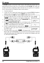
Page 88: ...not matter The CLONE CLONE CLONE CLONE CLONE notation will appear on the displays of both radios 4 On the Destination radio press the V M DW MT key WAI WAI WAI WAI WAIT T T T T will appear on the LCD 5 Press the BAND SCN BND DN key on the Source radio T T T T TX X X X X will appear on the Source radio and the data from this radio will be transferred to the other radio 6 If there is a problem durin...

Page 89: ...0 TN FRQ require that the 0 SET key be pressed after setting of the parameter and before exiting to normal operation MY MENU Short cut Key Setup In the factory default the primary press key function of the LK TXPO key is set to activating the Internet Connection feature However you may change the primary press key function of the LK TXPO key to a short cut path for recall of one of Set Mode Items ...

Page 90: ...Automatic ID EAI operating mode and its Transmit Time Enables Disables the Band edge beeper while selecting the fre quency via the DIAL knob Selects the alarm s utilized when the Emergency function is en gaged Reducing the Deviation level by 50 Selects the Primary function of the HM RV EMG R H key Selects the Access Number DTMF digit for WIRESTM operation Selects the Internet Link Connection mode ...

Page 91: ...and or Decoder mode Setting of the synthesizer steps Selects the measurement units for the altimeter and correcting the altimeter Selects the measurement units for the Barometric Pressure and correcting the Barometric Pressure Selects the display of the sensor units information Indicates indicate the current temperature inside the transceivre s case and selects the measurement units F or C for the...

Page 92: ...MF Autodialer Sets the Squelch threshold level Selects the Tone Encoder and or Decoder mode Setting of the CTCSS Tone Frequency ARTS SETTING Selects the Beep option during ARTS operation Selects the Polling Interval during ARTS operation Programs and activates the CW Identifier MEMORY SETTING Stores Alpha Numeric Tags for the Memory Group Enables Disables over written the Direct Memory Recall Chan...

Page 93: ... Selects the MONI switch just below the PTT switch function SU 1 SETTING Selects the measurement units for the altimeter and correcting the altimeter Selects the measurement units for the Barometric Pressure and correcting the Barometric Pres sure Selects the display of the sensor units information DISPLAY SETTING Indicates the DC Supply Voltage Setting of the Display brightness level Indicates in...

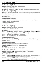
Page 94: ...T Function Selects the Polling Interval during ARTS operation Available Values 25 SEC 15 SEC Default 25SEC Set Mode Item 4 ARS Function Enables Disables the Automatic Repeater Shift function Available Values ARS ON ARS OFF Default ARS ON Set Mode Item 5 ATT Function Enables Disables the Receiver Front end 10 dB Attenuator Available Values OFF ON Default OFF Set Mode Item 6 BCLO Function Enables Di...

Page 95: ...n Shifting of the CPU clock frequency Available Values OFF ON Default OFF This function is only used to move a spurious response birdie should it fall on a desired frequency Set Mode Item 14 CW ID Function Programs and activates the CW Identifier used during ARTS operation See page 67 for details Set Mode Item 15 CWTRNG Function Enables Disables the CW Training feature and selects the sending spee...

Page 96: ...T Function Programming of the DTMF Autodialer See page 73 for details Set Mode Item 23 EAI Function Enables Disables the Emergency Automatic ID EAI Feature Available Values OFF ON Default OFF Set Mode Item 24 EAI TMR Function Setting of the Emergency Automatic ID EAI operating mode and its Transmit Time Available Values INT 1M through INT 10M INT 15M INT 20M INT 30M INT 40M INT 50M CON 1M through ...

Page 97: ...itted on the air beginning one minute after activation of the Emergency function BEEP Loud Alarm sounds STROBE The TX BUSY indicator lamp flashes When the radio is set to the CW or BP CW mode the radio will be instructed to send DE your callsign after the sending of the SOS message if your callsign is entered via Set Mode Item 14 CW ID CW ID CW ID CW ID CW ID Set Mode Item 27 HLF DEV Function Redu...

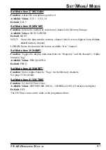
Page 98: ...LCD for five seconds when you rotate the DIAL knob or press any key or switch except the PTT switch CONT Illuminates the Keypad LCD continuously OFF Disables the Keypad LCD lamp illumination Set Mode Item 34 LED LT Function Illuminates the STROBE glows continuously in white useful as emergency flashlight at night Set Mode Item 35 LOCK Function Selects the Control Locking lockout combination Availa...

Page 99: ...t stored memory channel LOWER Stores the data into the lowest available free channel Set Mode Item 39 NAME Function Toggles the display indication between frequency and the channel s Alpha Numeric Tag Available Values FREQ ALPHA Default FREQ Set Mode Item 40 NM SET Function Stores Alpha Numeric Tags for the Memory channels See page 35 for details Set Mode Item 41 ON TMR Function Set the ON Timer t...

Page 100: ...omplete the message up to six characters 5 If you make a mistake press the BAND SCN BND DN key to back space the cursor now re enter the correct letter number 6 When you have entered the desired opening message press the 0 SET key mo mentarily to confirm the message then press the PTT key to save the settings and exit to normal operation Set Mode Item 43 PAGER Function Enables disables the Enhance...

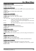
Page 101: ...s then will resume when the carrier drops HOLD The scanner will stop when a signal is received and will not restart Set Mode Item 50 RF SQL Function Adjusts the RF Squelch threshold level Available Values OFF S1 S2 S3 S4 S5 S6 S7 S8 S9 S9 Default OFF Set Mode Item 51 RPT Function Sets the Repeater Shift Direction Available Values RPT RPT SIMP Default Depends on the transceiver version as well as t...

Page 102: ...ets the magnitude of the repeater Shift Available Values 0 00 149 95 MHz 50 kHz increments Default Depends on the operating band and transceiver version Set Mode Item 57 SKIP Function Selects the Memory Scan Skip channel selection mode Available Values OFF SKIP ONLY Default OFF SKIP The scanner will skip the flagged channels during scanning ONLY The scanner will only scan channels that are flagged...

Page 103: ...p automatically changes according to operating frequency Set Mode Item 62 SU1 ALT Function Selects the measurement units for the altimeter require optional SU 1 and correcting the altimeter Available Values M meter Ft feet offset 1000 to 1000 Default Depends on the transceiver version Note OPTION OPTION OPTION OPTION OPTION will be displayed if the SU 1 is not installed Set Mode Item 63 SU1 BRM Fu...

Page 104: ...d Available Values FAST 2 5 tone sec SLOW 1 25 tone sec Default FAST Set Mode Item 70 TXSAVE Function Enables Disables the Transmitter Battery Saver Available Values OFF ON Default OFF Set Mode Item 71 VFO MD Function Enables or disables the VFO band edge limiting for the current band Available Values BAND ALL Default BAND BAND When the VFO frequency reaches the high band edge of the current band ...

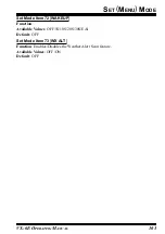
Page 105: ...AL 103 SET MENU MODE Set Mode Item 72 WAKEUP Function Available Values OFF 5S 10S 20S 30S EAI Default OFF Set Mode Item 73 WX ALT Function Enables Disables the Weather Alert Scan feature Available Values OFF ON Default OFF ...

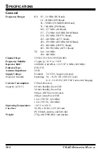
Page 106: ...ility 5 ppm 10 C to 50 C Repeater Shift 600 kHz 144 MHz 1 6 5 0 7 6 MHz 430 MHz Emission Type F2D F3E Antenna Impedance 50 Ω Supply Voltage Nominal 7 4 V DC Negative Ground Negative Ground Operating 5 0 16 0 V DC EXT DC Jack 11 0 16 0 V DC EXT DC Jack with Charging Current Consumption 150 mA Receive Approx 7 4 V 60 mA Standby Saver Off 30 mA Standby Saver On 900 µA ON Timer Activated 200 µA Auto P...

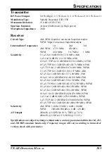
Page 107: ... 1 µV TYP for 12 dB SINAD 76 108 MHz WFM 1 5 µV TYP for 10 dB SN 108 137 MHz AM 0 2 µV for 12 dB SINAD 137 140 MHz FM 0 16 µV for 12 dB SINAD 140 150 MHz FM 0 2 µV for 12 dB SINAD 150 174 MHz FM 0 5 µV TYP for 12 dB SINAD 174 250 MHz WFM 0 5 µV for 12 dB SINAD 300 350 MHz NFM 0 2 µV for 12 dB SINAD 350 420 MHz NFM 0 18 µV for 12 dB SINAD 420 470 MHz NFM 1 µV for 12 dB SINAD 470 540 MHz WFM 1 µV TY...

Page 108: ...00 WFM 100 kHz 108 000 137 000 AM 25 kHz 137 000 160 600 FM 12 5 kHz 160 600 162 025 FM 25 kHz 162 025 174 000 FM 12 5 kHz FREQENCY RANGE MHZ MODE STEP 174 000 222 000 WFM 50 kHz 222 000 300 000 FM 12 5 kHz 300 000 320 000 AM 25 kHz 320 000 420 000 FM 12 5 kHz 420 000 430 000 FM 12 5 kHz 430 000 440 000 FM 25 kHz 440 000 470 000 FM 12 5 kHz 470 000 800 000 WFM 50 kHz 800 000 999 000 FM 12 5 kHz ...

Page 109: ...n the SU 1 with the transceiver s connector and gently press the unit into place 5 Affix the new supplied caution seal and replace the battery 6 Installation is now complete INSTALLATION OF THE SU 1 OPTION Important note The Barometric Pressure Altitude features of the optional SU 1 are designed to be supplemental aids for the information of the user and are not intended to be a substitute for acc...

Page 110: ...VX 6E OPERATING MANUAL 108 NOTE ...

Page 111: ...Printed in Japan Copyright 2005 VERTEX STANDARD CO LTD All rights reserved No portion of this manual may be reproduced without the permission of VERTEX STANDARD CO LTD 0505H 0M E H 0 2 1 M 2 0 0 ...

Reviews: