Chapter 4: Operation and Adjustment ES2 Series Servo User Manual Lite V1.0
23
4.2 Operating mode instructions
4.2.1 Position mode
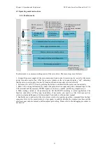
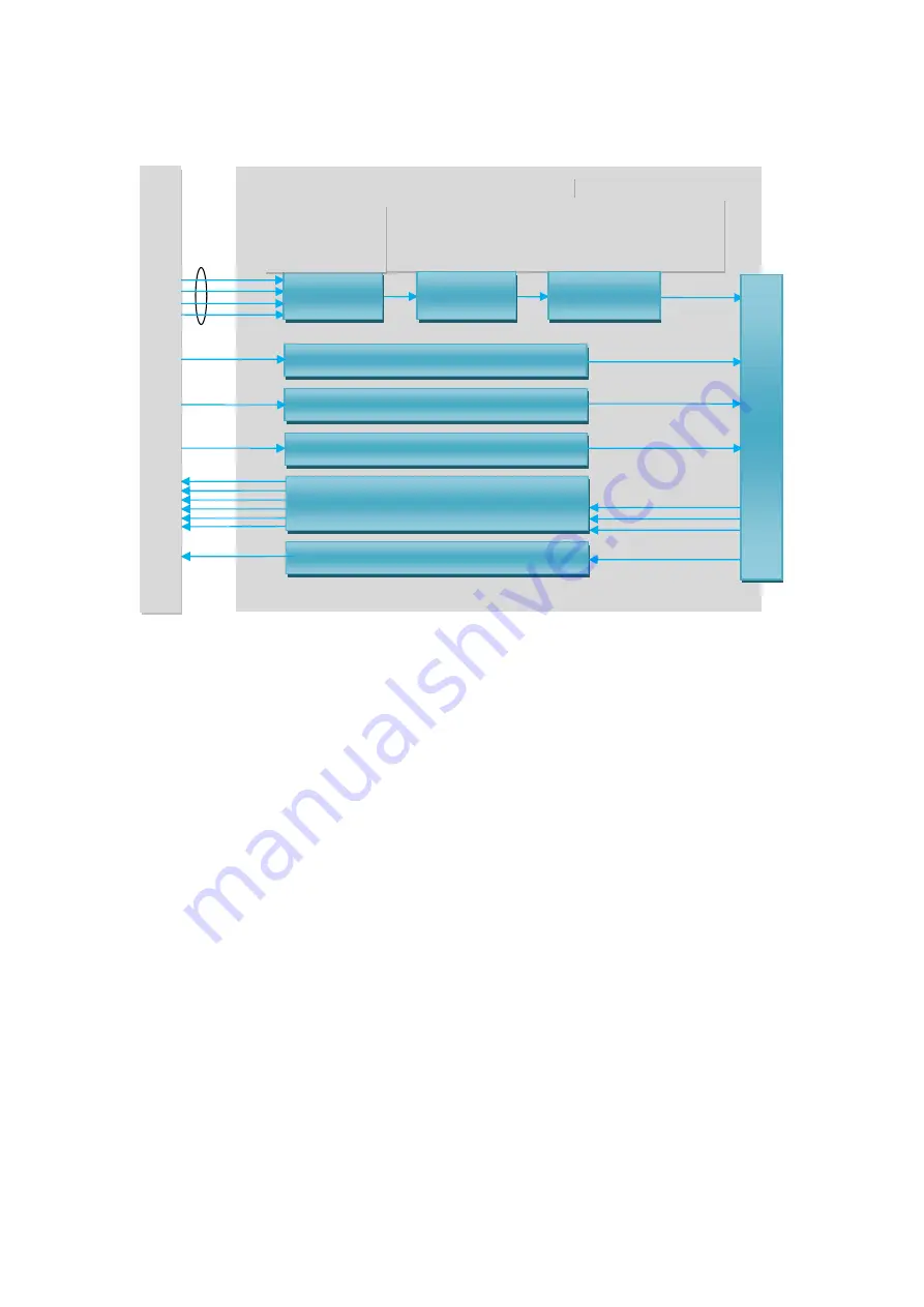
Position mode is a common working mode of the servo drive. The main steps are as follows:
1. Connect the power supply of the servo main circuit and control circuit correctly, as well as the motor
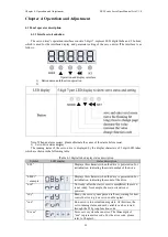
power line and encoder line. After the power is turned on, the servo panel displays “rdy”, indicating
that the servo power supply is correctly wired and the motor encoder is wired correctly.
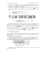
2. Perform a servo JOG test run by pressing the button to confirm that the motor can run normally.
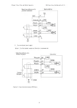
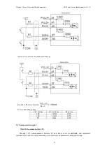
3. Refer to the wiring instructions to connect the pulse/direction input and pulse command input in the
CN1 terminal and the necessary DI/DO signals, such as servo enable, positioning completion, etc.
4. Make settings related to the position mode. Set the DI/DO according to actual application. The
function code refers to P02 group. In addition, if necessary, you need to set the functions such as
return-to-origin and frequency division output. For details, see the product manual.
5. Enable the servo and control the servo motor rotation by sending a position command from the host
computer. First, let the motor rotate at a low speed, to confirm whether the rotation direction and the
electronic gear ratio are normal, and then adjust gain setting. Please refer to the debugging procedure in
Section 4.4.
COIN output
Pulse divider output
PERR_CLR
input
INHIBIT
input
POS_DIR input
P04-23Positioning
completion output
P04-24
Positioning width
P04-07 gear ratio numerator 1
P04-09 gear ratio denominator 1
P04-11 gear ratio numerator 2
P04-13 gear ratio denominator 2
P04-05
Number of command pulses
required for one motor round
P04-03Position command
smoothing filter
P04-04
Position command
FIR filter
Pulse input
Command direction selection function
Pulse input inhibit function
Position deviation clear function
Command
input
Electronic
gear ratio
Position command
filtering
Positioning completed
P
os
iti
on
a
dju
stm
en
t c
on
tro
lle
r
Frequency division output function
P04-00
command
source
P04-21
command
form
H
os
t c
om
pu
te
r c
on
tro
lle
r


