Chapter 4: Operation and Adjustment ES2 Series Servo User Manual Lite V1.0
26
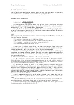
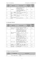
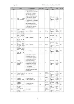
Set the electronic gear ratio according to the actual situation of the machine and the host computer.
Function
code
Name
Setting range
Min
unit
Factor
y
setting
Effective time
Type
Related
mode
P04
07
gear ratio numerator 1
1~1073741824
1
4
Immediately
Set
when
motor is
running
P
P04
09
gear ratio denominator
1
1~1073741824
1
1
Immediately
P
P04
11
gear ratio numerator 2
1~1073741824
1
4
Immediately
P
P04
13
gear ratio denominator
1
1~1073741824
1
1
Immediately
P
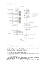
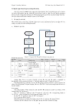
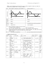
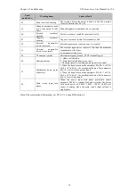
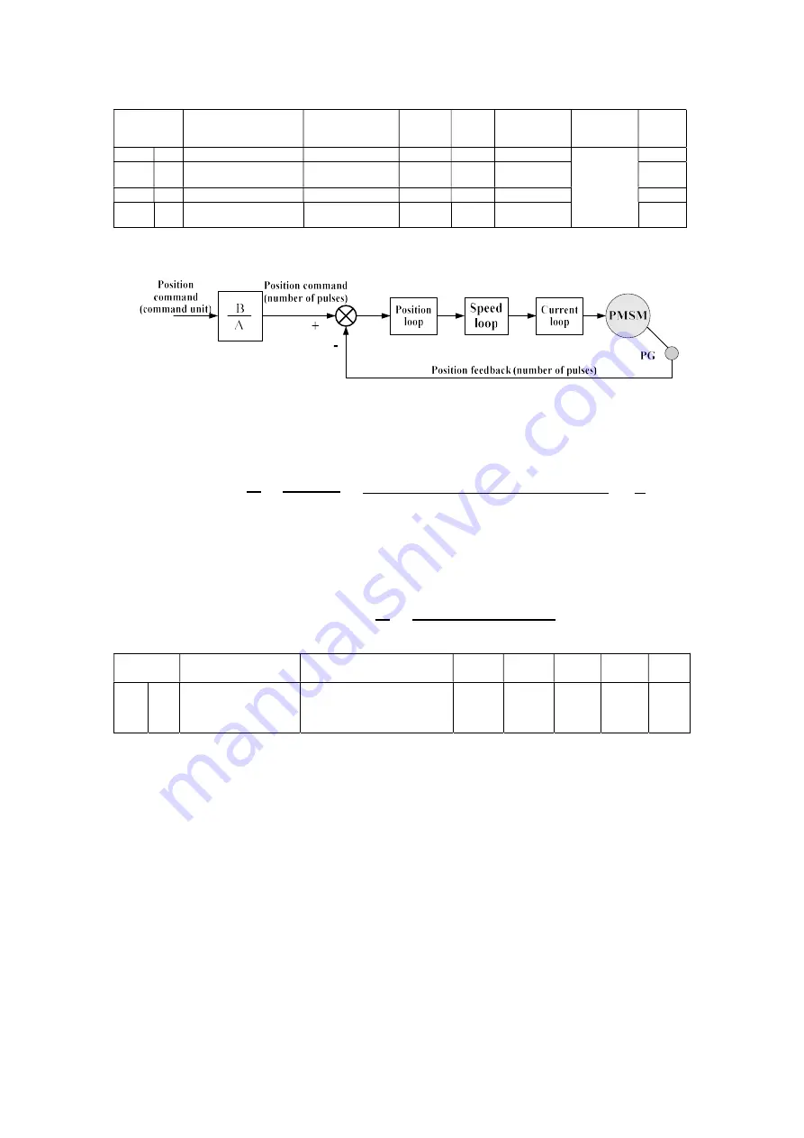
The schematic diagram of the electronic gear ratio is as follows:
a
)
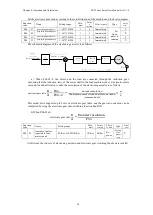
When P04-05=0, the motor and the load are connected through the reduction gear.
Assuming that the reduction ratio of the motor shaft to the load machine side is n/m (motor rotate
m round, load shaft rotate n round), the calculation of the electronic gear ratio is as follows :
electronic gear ratio
=
=
(
)
×
This model drive supports up to 2 sets of electronic gear ratios, and the gear ratio selection can be
completed by using the electronic gear ratio switching function FunIN.23.
b) When P04-05≠0:
electronic gear ratio
=
Function
code
Name
Setting range
Min
unit
Factory
setting
Effecti
ve time
Type
Related
mode
P04 05
Number of pulses
required for one
motor round
0P/Rev~1048576P/Rev
1P/Rev 0P/Rev
Re-
power
Setting
after
motor
stop
P
At this time, the two sets of electronic gear ratio and electronic gear switching function are invalid.


