7
Inspection and maintenance
07.2020
113
ba
-o
.2
.6
.0
-us
-3
.2
-ys
|
A1
18
67
50
1 Re
v A
E
7.13.3
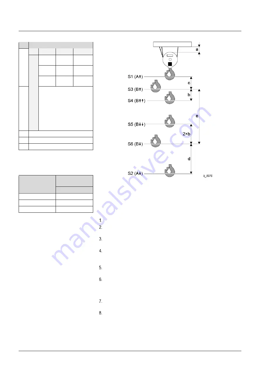
Checking the operational hoist limit switch - version 2 (S3)
Dim.
[in]
a
*1
50 Hz
60 Hz
Reeving
1PS
1PD
5.1
5.9
1
2PS
2PD
2.8
3.1
2
4PS
4PD
1.6
2
4
b
YK
/SK
with
frequen
cy
in
ve
rter
b = V × t × 0.023
ft
V = Hoist speed [fpm]
t = Brake ramp [s]
(Factory setting = 1.5 s
)
Example:
YKC/SKC-L05-
…S2
64
-V
b = 64 × 1.5 × 0.023 = 2.2
ft
c
*1
2.4
d
4.7
e
Effective hook path
*1
With the option
hook operated
hoist limit switch
(see section 4.12),
dimension “a” increases by 3.9
in,
dimension “c” increases in accordance with
the table.
Type
Dimension “c”
enlargement
[in]
YKA/SKA, YKB/SKB
2
YKC/SKC, YKE/SKE
3.9
YKD/SKD
5.9
Actuate the UP-button in the control pendant with caution.
Observe the hoisting movement, until the operational hoist limit switch switches off in
the top hook position (B
).
Prior to reaching the switch-off point (B
), make sure that a reduction to the slow
speed takes place (B
).
The minimum distance “a” + “c” between the hook block and the next obstacle, see
table, or hook aperture “C” (see section
7.15) must be maintained as a minimum,
depending on the dimension at which the hook hangs lower.
With deviations, adjust the geared limit switch again (see section
7.14 Adjusting the
switching points
).
Carefully actuate the DOWN-button in the control pendant whilst observing the
hoisting movement until the operational hoist limit switch switches off in the lower
hook position (B
). Prior to reaching the switch-off point (B
), make sure that a
reduction to the slow speed takes place (B
).
Mainta
in the minimum distance “d” between the switching point (B
) and (A
) (see
figure).
With deviations, adjust the geared limit switch again (see section
7.14 Adjusting the
switching points
).


