14
P/N 10001646 Rev. AA
June 2015
MAINTENANCE (CONTINUED)
YALELIFT 360™ ATEX ITP/ITG, UP TO 5 TON
The trolleys are built to fit beam range A or B which is indicated on
the identity plate. Before installation, make sure that the track beam
width is within this beam range.
The further procedure for assembly of the unit on the track beams
depends on whether the track beam has an accessible open end
or not. If this is the case, it is recommended that the unit be pre-
assembled on the ground and then be pushed onto the open end of
the beam.
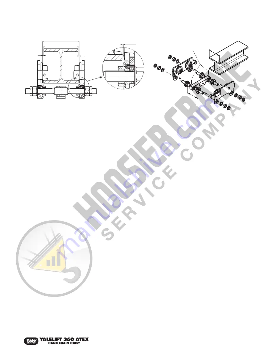
1. Unscrew locking nuts and hexagonal nuts from the suspension
bolt and remove both side plates from the trolley.
2. Measure flange width “b” of the track beam.
3. Adjust or pre-adjust dimension “B” between the outer flanges of
the round nuts on the four free threaded ends of the suspension
bolts. Make sure that the four drill holes in the round nuts face
outwards. Select dimension “B” between the outer flanges of
the round nuts on the suspension bolts in such a way that it
corresponds to flange width “b” plus 4 mm. Ensure that the
suspension bar is centered between the round nuts.
4. Assembly of one side plate: The roll pins fitted to the side plate
must be seated in one of the four drill holes of the round nuts.
If necessary the position of the round nuts must be slightly re-
adjusted.
5. Position the washer and tighten the hexagonal nuts. Finally
screw on the locking nuts by hand and tighten by ¼ to ½
rotation.
ATTENTION: The locking nuts must always be fitted!
6. Place the second side plate onto the suspension bolts without
tightening. Then screw on washers, hexagonal nuts and locking
nuts without tightening to facilitate assembly.
7. Place the entire pre-assembled unit onto the beam.
ATTENTION: For Yalelift ITG models, pay attention to the
position of the gear drive.
8. Insert the roll pins driven into the second side plate in one of the
appropriate four drill holes of the round nuts. If necessary the
round nuts must be slightly re-adjusted.
9. Tighten the hexagonal nuts on the second side plate. Finally
screw on the locking nuts by hand and tighten by ¼ to ½
rotation.
ATTENTION: The locking nuts must always be fitted!
10. Check the fitted unit:
a) The lateral play dimension “A” must not exceed 2 mm between
the wheel flange and the outer edge of the beam.
b) The suspension bar must be positioned centrally between the
side plates.
c) All nuts and locking nuts must be firmly tightened.
YALELIFT 360™ ATEX ITG 5 & 6 TON
1. Measure the flange width of the beam.
2. Evenly distribute the spacer sleeves and spacer washers
on both sides of the suspension bolt accordingly. A clearance
("A") of 2 mm between the wheel flange and the beam flange
must be maintained (inner dimension = flange width + 4 mm).
3. After adjustment of the inner dimension, evenly distribute the
remaining spacer sleeves and spacer washers on the outside of
the side plates on the suspension bolt. In each case, at least 3
spacer washers and 1 spacer sleeve must be mounted between
the side plates and the castle nut.
Tip: For easier assembly, tighten one side plate. Observe the
required position of the drive side. Only slide on the other side
plate without tightening.
4. Then lift the entire unit onto the track beam and firmly tighten all
castle nuts.
5. Secure all castle nuts with cotter pins.
ATTENTION: A trolley must never be used on a beam with a flange
width that exceeds the maximum adjustable width of the trolley
(observe total clearance of 5 mm, depends on model) or with a
profile which does not correspond to the profile the trolley has been
designed for.
SHORTEN OR EXTEND THE HAND CHAIN
Adjust the length of the hand chain so that the distance of the lower
end to the floor is between 20 to 40 in. (500 to 1000 mm).
NOTE: For safety reasons, hand chain links may only be used once.
1. Look for the non-welded link of the hand chain, bend to open
and discard it.
2. Shorten or extend the chain to the required length.
ATTENTION: Always remove or add an even number of chain links.
3. Use a new link to close the loose chain ends by bending it (for
extending the hand chain, two new chain links are required).
ATTENTION: Do not twist hand chains while fitting.
TROLLEY DISASSEMBLY AND ASSEMBLY
A
A
A
B
b
b
Locking Sleeve
B


