background image

5

P/N 10001646 Rev. AA  

June 2015

GENERAL SAFETY INFORMATION 

(CONTINUED)

MOVING HAZARDOUS LOADS

The hoists are not recommended for lifting materials that could 

cause widespread damage if dropped. The lifting  

or moving of materials that could explode or cause  

chemical or radioactive contamination requires fail-safe, 

redundant supporting devices that are not incorporated  

into these hoists. 

TEMPERATURE LIMITS IN EXPLOSIVE

ATMOSPHERES AND DUSTS

In order to determine the maximum surface temperature, 

several tests have been performed with nominal load under 

extreme conditions. The maximum surface temperature has 

been determined at a room temperature of 68°F (20°C) to 72°F 

(22°C) without dust deposit and without safety factors!
Based on these tests, the Yalelift range has been classified 

in temperature class T4 (275°F/135°C maximum surface 

temperature) for gases. The relevant values for dusts can be 

found on page 2. 
These values refers to a lowering process of up to 10 m without 

disruption. For longer lowering processes, e.g. 15 m or more, 

breaks must be made for cooling.
The hoist may be used at ambient temperatures between  -4°F 

(–20 C°) and 104°F (40°C). Consult the manufacturer in the case 

of extreme working conditions.
The temperature range refers to -4°F (–20°C) up to 104°F 

(40°C). In case of deviating loading or temperature ranges 

consult the manufacturer.

Units for operation in areas with potentially explosive 

gases/air resp. steam/air atmospheres or inflammable 

mist

The temperatures of all equipment, protective systems 

and components surfaces which can come into contact 

with explosive atmospheres must not exceed the ignition 

temperature of the combustible gas or liquid during normal 

operation and in the case of malfunctions. However, where it 

cannot be excluded that the gas or vapor can be heated to the 

temperature of the surface, this surface temperature must not 

exceed 80% of the ignition temperature of the gas measured 

in °C. This value may only be exceeded in the case of rare 

malfunctions.

Units for operation in dust /air atmospheres

In areas, which are explosive by inflammable dusts, the surface 

temperature must not exceed 2/3 of the minimum ignition point 

in degrees Celsius (°C) of the dust/air mixture. Temperatures 

of surfaces, which can be subject to dangerous deposits of 

ignitable dusts, must be one safety margin lower than the 

minimum ignition temperature of the layer which can possibly 

be generated by the respective dust. This requires a safety 

margin of 75 K between the minimum ignition point of a dust 

deposit (ignition temperature) and the surface temperature of 

the unit. If the dust deposit exceeds a thickness of 5 mm, larger 

safety margins are required.
Combustion and explosion characteristics of dusts:
Starch / milk powder / gelatine 

Ignition temperature 390 °C x 2/3 = 260 °C max. permissible 

surface temperature.
Wood / grinding dust 

Ignition temperature 290 °C - 75 °C = 215 °C max. permissible 

surface temperature.

Classification of the hoists

After intensive testing under extreme conditions the hoist series 

Yalelift can be classified for correct operation in the general 

industry as follows on page 2. The documents have been 

checked by a nominated body and deposited at  

TÜV Rheinland Industrie Service GmbH, Haumannplatz 4, 

45130 Essen.

IDENTIFICATION

In order to exactly identify the product, you will find the identity 

plate with all pertinent data on the gear cover. In case of queries 

with regard to handling the product, which are not covered by 

these operating instructions, please contact:
COLUMBUS McKINNON CORPORATION 

140 John James Audubon Parkway 

Amherst, NY 14224  U.S.A  

Phone: 800-888-0985 • Fax: 716-689-5644 

www.cmworks.com 

SPARK FORMATION

Materials subject to danger of friction and impact

Individual sparks can be generated as a result of frictional 

and/or impact processes and, as a consequence, can be the 

cause dangers of ignition in gases or impact-sensitive dusts. 

Increased danger of ignition may emanate from clashing of 

special material pairings. These are non corrosion-resistant 

steel or cast iron against magnesium or pertinent alloys. This 

applies especially in case of rust (e.g. surface rust).

Especially at the friction points of the chain and load hook 

rust (surface rust) may occur. For correct operation of the 

product it must therefore be ensured that there is no rust at 

these wear points and that in the application area there are 

no material combinations of the above-mentioned aluminium 

alloys and steel (exception: antirust steel) at possible friction, 

impact or grinding points; thus spark formation by these 

material combinations as a result of mechanical impact can be 

excluded. 

Hand and load chain

Always ensure that the hand chain, load chain and the load are 

guided to exclude grinding and/or sliding contact with external 

constructions or components. Depending on the degree of 

corrosion, the conductive discharge capability of hand chains 

and/or load chains can worsen to an effect that it is not 

adequate any longer. For operation this means that rusty hand 

chains and/or load chains must no longer be used.
Attention: The user has to operate the unit to avoid sparking from the 

hand chain as well as from the load chain. YLITP/YLITG models must 

always be operated from below. 
For additional safety and to avoid sparking by impact or friction 

during operation, the units are equipped with stainless steel 

hand chains.
Units have copper-plated top and bottom hooks and are fitted 

with stainless steel load chain.
Trolleys are always provided with buffer and solid bronze 

wheels. Geared trolleys are equipped with stainless steel hand 

chain.

Attachment points

Attachment points have to be selected to ensure that the 

expected forces can be safely absorbed. The unit must align 

freely under load in order to avoid impermissible additional 

loading.

STATIC ELECTRICITY

In order to avoid electrostatic charging on plastic parts, the 

user should wear suitable protective clothing, e. g. conductive 

footwear, clothes and gloves. It is also advised that the product 

is used on a conductive floor.
Cleaning only with a damp cloth (when cleaning these 

components, make sure to apply only materials which do not 

allow electrostatic charging).
Special feature of hydrogen (explosion group IIC): Hydrogen 

only requires an extremely small energy for ignition. For this 

reason, we recommend that prior to application of the unit a 

release measurement be carried out. The spark for ignition may 

be generated electrostatically or mechanically by handling of a 

tool, for example.

Summary of Contents for YALELIFT 360 ATEX

Page 1: ...k is greatly increased if proper instructions and warnings are not followed Before using this hoist each operator should become thoroughly familiar with all warnings instructions and recommendations in this manual Retain this manual for future reference and use Forward this manual to operator Failure to operate equipment as directed in manual may cause injury II 2 GD c IIC T4 ATEX RATING Rated Loa...

Page 2: ... 888 0985 fax 716 689 5644 or visit www cmworks com Protection Classification II 2 GD c IIC T4 Hand Chain Material Stainless Steel Load Chain Material Stainless Steel Load and Top Hook Copper plated Trolley Trolley with Buffer Roller Bronze Plain Roller CLASSIFICATION FOR CORRECT OPERATION MAXIMUM SURFACE TEMPERATURE OF THE EQUIPMENT FOR CORRECT OPERATION IN DUSTY ENVIRONMENTS II 2 GD c IIC T4 II ...

Page 3: ... checked for deposits of foreign material which may be carried into the hoist mechanism Check brake for evidence of slippage under load DO NOT LIFT MORE THAN RATED LOAD DO OPERATE WITH MANUAL POWER ONLY ONE OPERATOR DO NOT OPERATE DAMAGED OR MALFUNCTIONING HOIST DO NOT OPERATE WITH TWISTED KINKED OR DAMAGED CHAIN DO NOT PULL AT AN ANGLE BE SURE HOIST AND LOAD ARE IN A STRAIGHT LINE DO NOT USE LOAD...

Page 4: ...s are missing or illegible 27 Be familiar with operating controls procedures and warnings Improper operation of a hoist can create a potentially hazardous situation which if not avoided could result in minor or moderate injury To avoid such a potentially hazardous situation the operator shall 1 Maintain a firm footing or be otherwise secured when operating the hoist 2 Check brake function by tensi...

Page 5: ...cked by a nominated body and deposited at TÜV Rheinland Industrie Service GmbH Haumannplatz 4 45130 Essen IDENTIFICATION In order to exactly identify the product you will find the identity plate with all pertinent data on the gear cover In case of queries with regard to handling the product which are not covered by these operating instructions please contact COLUMBUS McKINNON CORPORATION 140 John ...

Page 6: ...9 156 175 167 164 242 24 70 97 125 19 1 2 20 47 1 50 1 58 8 66 9 84 8 62 8 86 13 19 1 34 3 74 4 88 7 01 1 18 520 38 40 220 250 219 225 335 34 95 124 178 30 3 4 25 75 1 77 1 85 8 66 9 84 8 62 9 53 13 86 0 83 3 74 4 88 11 22 1 46 654 45 47 220 250 219 242 352 21 95 124 285 37 5 6 32 48 2 68 2 68 8 66 15 08 8 62 12 84 17 17 5 35 3 74 4 88 15 79 1 97 825 68 68 220 383 219 326 436 136 95 124 401 50 8 1...

Page 7: ... 132 5 445 180 256 112 112 320 440 3 4 21 65 10 26 1 77 1 85 1 46 5 89 1 20 5 61 5 85 20 67 8 23 11 14 M 42 4 92 4 61 14 33 19 06 550 260 5 45 47 37 149 5 30 5 142 5 148 5 525 209 283 125 117 364 484 5 6 30 87 14 96 2 68 2 68 1 97 4 45 2 17 6 65 6 65 16 93 7 87 10 28 M 48 5 91 6 22 21 26 784 380 68 68 50 113 55 169 169 430 200 261 150 158 540 HOIST WITH INTEGRATED TROLLEY Dimensions for 8 10 12 to...

Page 8: ...is manual and specifically excludes hoists subject to normal wear abuse improper installation improper or inadequate maintenance hostile environmental effects and unauthorized repairs modifications We reserve the right to change materials or design if in our opinion such changes will improve our product Abuse repair by an unauthorized person or use of replacement parts not supplied by Columbus McK...

Page 9: ...ad or use correct capacity hoist NOTE The load limiting device incorporated in this hoist is effective only when the overload is being lifted or pulled through the operation of the handwheel It will not protect against externally applied overloads 5 Do not wrap load chain around the load or bring the load in contact with the hoist Doing this will result in the loss of the swivel effect of the hook...

Page 10: ...F CHAIN TO LOWER HOOK PULL ON THIS PART OF CHAIN UPPER HOOK HAND CHAIN LOAD CHAIN LOWER HOOK HOIST FRAME HOIST LATCH SUSPENSION BOLT SIDE PLATE TROLLEY WHEEL SUSPENSION BAR ROUND NUT LOCKING SLEEVE WASHER HEX NUT LOCKING NUT SUSPENSION BOLT SIDE PLATE TROLLEY WHEEL SUSPENSION BAR GEAR DRIVE ROUND NUT LOCKING SLEEVE WASHER HEX NUT LOCKING NUT HAND CHAIN WHEEL HOIST TROLLEY COMPONENT OVERVIEW ...

Page 11: ...new Columbus McKinnon parts before the unit is returned to service It is very important that the unserviceable parts be destroyed to prevent possible future use as a repair item and properly disposed of Hook Inspection Hooks damaged from chemicals deformation or cracks or that have a twist excessive opening or seat wear must be replaced Also hooks that are opened to the extent that the latch does ...

Page 12: ...iplex 2 Century Lubricants Co grease or equal lubricant to the exterior surface of the drive shaft gears internal thread of brake hub surface of liftwheel bushings 1 2 ton unit bushings in the gear side plate and gear cover internal and external surfaces of handwheel bushings and rim of handwheel cover IMPORTANT To assure long life and top performance be sure to lubricate the various parts of the ...

Page 13: ...brake hub Slide Belleville spring washer pressure plate front brake disc handwheel and rear brake disc from handwheel brake hub Inspect both brake discs and replace if excessive wear scoring glazing or contamination is found If brake disc is worn down to the following thickness replacement is required Capacity ton Thickness Min in mm 1 1 2 043 1 1 3 4 5 6 8 10 12 063 1 6 Inspect pressure plate han...

Page 14: ...agonal nuts on the second side plate Finally screw on the locking nuts by hand and tighten by to rotation ATTENTION The locking nuts must always be fitted 10 Check the fitted unit a The lateral play dimension A must not exceed 2mm between the wheel flange and the outer edge of the beam b The suspension bar must be positioned centrally between the side plates c All nuts and locking nuts must be fir...

Page 15: ...mbly However for proper operation of the 1 1 2 3 4 5 6 8 10 and 12 ton units one gear marked A and one gear marked B must be used PREVENTIVE MAINTENANCE In addition to the inspection procedures a preventative maintenance program should be established to prolong the useful life of the hoist and maintain its dependability and continued safe use The program should include the periodic inspections wit...

Page 16: ... or build up of foreign material Pockets of Liftwheel Stripper and Side Plates Cracks distortion excessive wear corrosion or build up of foreign material Nuts Screws Pins and Cotter Pin Cracks bending loose stripped threads Brake Spring Corrosion stretched or broken Loose End Connector Missing cracked not secured to chain not properly positioned Nameplate Warning Labels and Free Chaining Missing D...

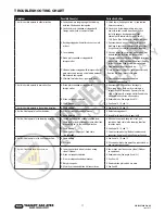
Page 17: ...ts corroded or clogged with foreign matter A Disassemble brake and clean thoroughly By wiping with a cloth not by washing in a solvent Replace brake disc if gummy visibly worn or coated with a foreign matter Keep brake disc and brake surfaces clean and dry B Brake not properly adjusted B Readjust brake See pages 9 and 10 C Chain binding C See Items 1A 1B and 1C 3 Hoist is hard to operate in the ho...

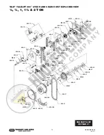
Page 18: ...56 30 656 33 656 29 656 15 656 18 656 8 656 43 656 13 656 28 656 5 656 39 656 39A 656 19 656 1 656 12A 656 11B 656 14 656 12B 656 11A 656 11 656 2 656 18 656 4A 656 4 656 6 656 7 656 16 656 17 656 27A 656 20 656 41 656 26 656 21 656 26 656 22 656 27 656 23 656 31 656 32 656 34A 656 34A 656 35 656 19 656 36 656 36 SEE PARTS LIST ON PAGE 21 ...

Page 19: ...56 11 656 2 656 18 656 4A 656 4 656 6 656 7 656 17 656 27 656 22 656 23 656 29 656 33 656 30 656 15 656 8 656 18 656 9 656 44 656 42 656 43 656 10 656 11B 656 12A 656 1 656 14 656 24 656 5 656 13 656 27A 656 41 656 26 656 21 656 26 656 20 656 31 656 32 656 34A 656 34A 656 19 656 35 656 28 656 36 656 36 656 15 SEE PARTS LIST ON PAGE 21 ...

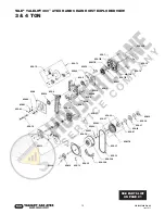
Page 20: ...56 18 656 2 656 11 656 11A 656 11B 656 12B 656 19 656 39 656 20 656 26 656 21 656 26 656 22 656 27A 656 27 656 23 656 31 656 32 656 34A 656 31 656 33 656 29 656 36 656 36 656 19 656 35 656 34A 656 41 656 18 656 10 656 28 656 8 656 39A 656 13 656 15 656 16 656 9 656 44 656 43 656 42 656 1 656 12A 656 14 656 24 656 15 SEE PARTS LIST ON PAGE 21 ...

Page 21: ...N09151121 N09151121 N09151121 2 656 19 Screw N09102264 N09108020 N09108020 N09108020 8 656 20 Disc hub N00401223 N00401267 N00401267 N00401267 1 656 21 Ratchet disc assembly N00401311 N00401313 N00401313 N00401313 1 656 22 Hub N00401682 N00401684 N00401684 N00401684 1 656 23 Screw N00402215 N00402216 N00402216 N00402216 3 656 24 Roller set N00400756 N00400756 1 656 26 Friction disc N00401534 N0040...

Page 22: ...656 3 656 5 656 25 656 19 656 30 656 28 656 24 656 16 656 20 656 33 656 4 656 12 656 9 656 15 656 26 656 11 656 2 656 32 656 10 656 36 656 35 656 7 656 21 656 34 656 23 656 31 656 27 656 12 656 24 656 22 656 33 656 1 656 18 656 4 656 17 656 29 656 5 656 14 656 6 656 13 656 3 SEE PARTS LIST ON PAGE 23 ...

Page 23: ...orting bolt N00550147 2 656 15 Axle support N00402169 2 656 16 Axle support N00402170 4 656 17 Axle support N00402171 2 656 18 Side cover N00402172 2 656 19 Side cover support N00402173 2 656 20 Cover plate for bottom block N00402174 1 656 21 Distance ring N00402175 5 656 22 Name plate ATEX with classification II 2 GD c IIC T4 192021878 8 ton 1 192021879 10 ton 1 192021881 12 ton 1 656 23 Capacity...

Page 24: ... 2 4 Nut 00552051 00552053 4 5 Roller without geared 00500005 00500007 4 6 Bearing 09151074 09151046 4 7 Retaining ring 09130024 09130046 4 8 Retaining ring 09129029 09129002 4 9 Name plate 192022393 192022393 1 10 Round head grooved pin 09128004 09128004 4 11 Nut 09115152 09115154 4 12 Nut 09115089 09115090 4 13 Washer 09121021 09121016 4 14 Spring pin 09134055 09134054 4 15 Bolt 00552110 0055014...

Page 25: ...00552089 00552088 1 10 Hand chain guide 00552090 00552091 00552092 1 11 Retaining ring 09129029 09129002 09129003 4 12 Bearing 09151074 09151046 09151079 4 13 Retaining ring 09130024 09130046 09130060 4 14 Nut 09115152 09115154 09115155 4 15 Nut 09115089 09115090 09115156 4 16 Washer 09121021 09121016 09121213 4 17 Spring pin 09134055 09134054 09134120 4 18 Screw 09101052 09101050 09101050 2 19 Wa...

Page 26: ...n assy 00530016 1 11 Clevis foot 00530077 1 12 Hand chain wheel 00530078 1 13 Hand chain guide 00530079 1 14 Groove ball bearing 09150020 8 15 Retaining ring 09129010 4 16 Cap 00530008 4 17 Retaining ring 04307654 4 18 Castle nut 00530014 2 19 Washer 00530013 6 20 Cotter pin 09125035 2 21 Screw 09101038 2 22 Lockwasher 09122016 2 23 Name plate 192022393 1 24 Capacity plate 1 25 Round head grooved ...

Page 27: ...ion assy 00530016 2 11 Clevis foot 00530077 2 12 Hand chain wheel 00530078 2 13 Hand chain guide 00530079 2 14 Groove ball bearing 09150020 16 15 Retaining ring 09129010 8 16 Cap 00530008 8 17 Retaining ring 04307654 8 18 Castle nut 00530014 4 19 Washer 00530013 12 20 Cotter pin 09125035 4 21 Screw 09101038 4 22 Lockwasher 09122016 4 23 Name plate 192022393 1 24 Capacity plate 1 25 Round head groo...

Page 28: ...ial number of hoist on which the parts are to be used For the location of the nearest Columbus McKinnon Master Parts Depot vcall 800 888 0985 fax 716 689 5644 or visit www cmworks com prior to such damage injury or loss such goods are 1 damaged or misused following Seller s delivery to carrier 2 not maintained inspected or used in compliance with applicable lcaw and Seller s written instructions a...

Reviews: