Page 12
5-4. INSPECT ELECTRICAL CONTROLS. Arrangement of
electrical control equipment varies with the type of control,
physical space and the optional control features ordered with
the hoist.
Note the location in the electrical compartment of the control
circuit fuse, transformer, limit stop switches and the hoist
contactors. Trolley contactors and optional hoist and trolley
fuses may also be located in this compartment on certain
models. (Note: The rope anchor on single reeved hoists is
accessible from this compartment.)
Hoist and trolley fuses and trolley contactors may be located in
electrical compartment located on trolley on certain models.
Use wiring diagram furnished with hoist to determine electrical
components on your hoist; then determine component location
and identity on your hoist.
Be certain that main power switch is locked in open
position before opening hinged access cover on side
of hoist.
WARNING
Check to be certain main power switch is locked in
open position before removing brake cover.
WARNING
a. Open hinged access cover at side of hoist and inspect
wiring and terminals. Terminals should be securely
crimped to wires and insulation sound. Terminal screws
should be tight.
b. Check condition of contactor assembly, transformer, and
upper limit switches.
5-5. INSPECT MOTOR BRAKE AND ACTUATING
MECHANISM.
a. Remove one hex button head cap screw from brake cover
and lift brake cover away from gearcase cover.
b. Unplug electrical leads and loosen set screw in gearcase
cover (Ref. No. 1 in Figure 9-6). Turn actuating mechanism
counterclockwise, by hand or with a plumber’s strap
wrench, and remove from gearcase cover.
c. Check to see that brake plunger moves freely. Inspect for
evidence of overheating or other damage.
d. Replace all worn or damaged parts. Operating spring on
actuating mechanism is color coded for brake torque;
when replacing spring use spring having same color code.
When replacing body assembly, also replace brake
operating spring.
e. Reassemble brake and cover only if further disassembly
to check friction surfaces and hub spline is not required
at this time. Refer to “MOTOR BRAKE ADJUSTMENT’
paragraph 7-2 for adjusting instructions. For further
disassembly proceed to step “f.”
f. To check motor brake friction surfaces (Figure 5-3), drain
oil from gearcase. Disconnect solenoid coil leads. Remove
hex head cap screws securing gearcase cover to
gearcase. Remove gearcase cover and attached motor
brake actuating mechanism from gearcase.
g. Remove retaining rings from the brake pilot studs and lift
off the compression plate. Lift off washer and lining
assemblies, release springs, and motor brake plates. (Note
for reassembly, that two of the washer and lining
assemblies have friction surfaces on one side only and
must be replaced at each end. Three washer and lining
assemblies, with friction surfaces on both sides and
release springs are replaced between the motor brake
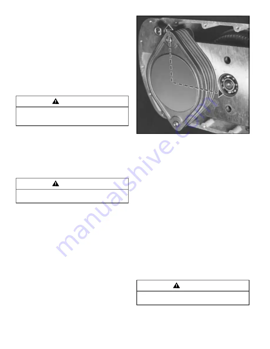
plates; see Figure 5-3). Check motor brake plates for
warping, scoring or other signs of deterioration. Also check
spline fit of motor brake plates to the brake hub for
gouging, mushrooming of the plates or other signs of
distress or wear. Replace plates if these conditions are
found. Brake plates which are replaced because of spline
wear should also receive a replacement brake hub. Check
condition of friction material on the washer and lining
assemblies, and replace assemblies if required. Reinstall
brake plates, release springs, and friction washers in
sequence as shown in Figure 5-3 and replace retaining
rings. On the Size 3 hoist it is possible to get the lining
assemblies misoriented. When installed properly the
friction linings will be on a horizontal line (not vertical).
Clean and flush gearcase and replace gearcase cover
using a new gasket. Refill with new lubricant.
5-6. INSPECT MECHANICAL LOAD BRAKE AND GEARING.
Check to be certain main power switch is locked in
open position before removing brake cover.
WARNING
Figure 5-3. Motor Brake Friction Plates
11988
a. To inspect hoist, drain oil from gearcase, remove motor
brake actuating mechanism per Paragraphs 5-5.a and 5-
5.b, remove hex head cap screws from gearcase cover,
and remove gearcase cover.
Summary of Contents for SHAW-BOX
Page 66: ...NOTES ...
Page 67: ...NOTES ...


