


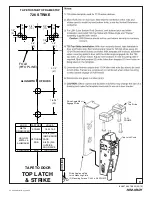
Top Latch & 791or 726
Strike Template
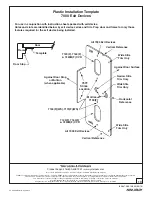
Device Template
Floor Strike Template
FINISHED FLOOR or THRESHOLD
Bottom Case
Template
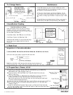
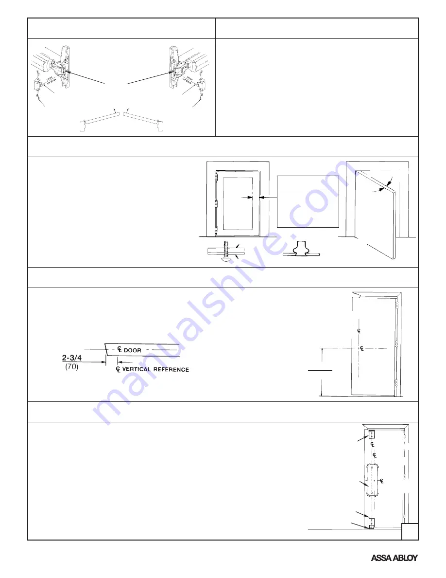
To Change Hands
Check Before Starting
Unreinforced Doors or Frames
Doors and Frames with walls having a structural
thickness (metal skin plus reinforcement or solid
hardwood) to engage less than (3) full screw threads
are considered unreinforced.
Unreinforced Doors: Use SNB (sex nuts and bolts).
Unreinforced Frames: Use Blind Rivet Nuts.
Recommended fasteners for unreinforced openings
are not necessarily supplied by Yale Locks and
Hardware.
Reinforcement
Door Skin
Blind Rivet Nut
Door Must Swing Freely
Min. Door Stile
4-1/2" (114mm)
Maintenance
1.
Periodically remove covers and coat mechanisms with a
silicone base lubricant. This is particularly required in corrosive
environments for proper product function.
2.
Check mounting fasteners periodically. Retighten if found
loose. Apply screw locking compound (available at automotive
part stores) or change part fasteners if screws continue to back
out.
3.
Periodic checks (and adjustments) of strikes are required to
compensate for changes in the opening (e.g. door sagging).
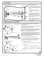
1. Mark Door
Door and frame must
meet structural and
dimensional specifications
on exit device template(s)
for door and frame
preparation.
2. Prepare Door, Frame, & Sill
(4) 8-32 x 3/16" PPHMS
Vertical Lifter Assembly
Remove (4) Screws and
Vertical Lifter Assembly.
Rotate device to opposite
hand (180 degrees). Insert
Lifter Assembly under Lift
Block and re-install screws.
Lift Block
Single Door or Pair without Mullion
Locate and Mark Horizontal and Vertical Reference Centerlines as shown.
LHR door shown, preparation is typical for both door hands.
Note:
Door should be in the closed position while marking horizontal and
vertical reference lines. Paper or the Plastic Template may be used in this step.
FINISHED
FLOOR
or THRESHOLD
A.
Locate “Device Template” aligning VERTICAL REFERENCE and HORIZONTAL
REFERENCE lines. Tape template to door face.
B.
Extend centerline of Rod and Strikes from “Device Template” to door top and
bottom, on door face.
C.
Locate Top Latch/Strike and Bottom Bolt Case templates in place over centerline
of Rods and Strikes on door. Tape templates in place and mark holes.
Note that the centerline of the rods and strikes used to install top and bottom bolts
is not the Vertical Reference centerline.
D.
Locate and tape Trim Template to door when required (See instructions packed with Trim).
E.
Mark and prepare holes per installation template (exclude 791 or 726 strike, holes
prepared in Step 7).
F.
Locate 790 Bottom Strike Template. Tape in place over Rods and Strikes centerline
on door. Tape template in place and mark hole locations. Holes to be prepared in Step 7.
G.
Remove templates from door.
LHR Device
LHR Door
RHR Door
Vertical Lifter Assembly
(4) 8-32 x 3/16" PPHMS
RHR Device
LHR DOOR
INSIDE FACE
VERTICAL
REFERENCE
HORIZONTAL
REFERENCE
39-15/16
(1014)
LHR DOOR
INSIDE FACE
VERTICAL
REFERENCE
HORIZONTAL
REFERENCE
Rods & Strikes
2
An ASSA ABLOY Group brand
80-9470-0010-000 (03-13)


