


3
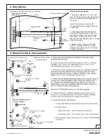
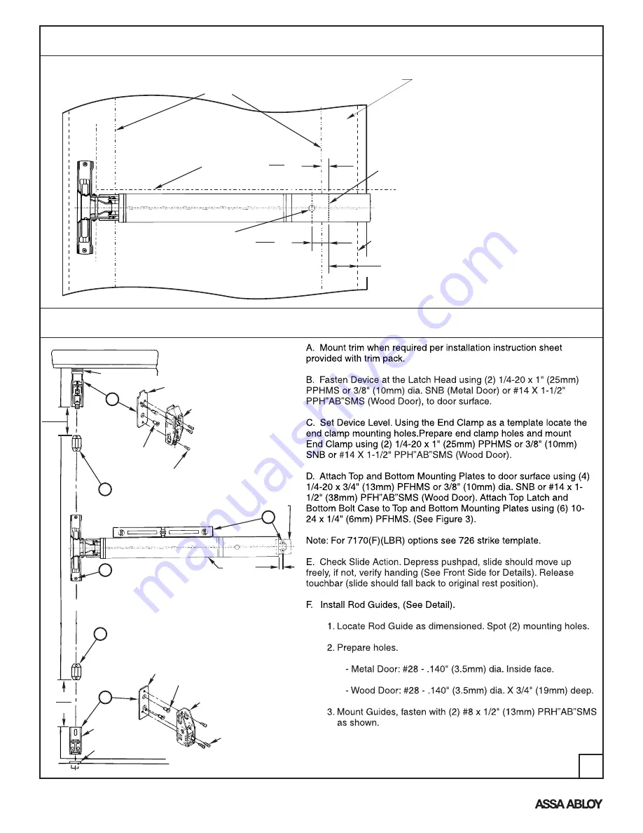
4. Mount Device & Components
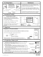
3. Size Device
Device must be field cut to size, as required
HINGE SIDE OF DOOR
C
L
STILE
* LHR Door (Door Open)
inside face
STOP
SURFACE
CUT
LINE
2-1/4
(57)
1-3/8
(35)
Min.
Horizontal line
Dogging
Hole
3/8
(10)
Min.
Determine device length
1. Close door. Measure 2-1/4" (57mm)
from the Stop Surface on the hinge side of
the door, mark Horizontal Reference at
this point.
Note: This dimension must be 3/8"
(10mm) minimum from edge of the stile
on the door.
2. Open door. Align mounting holes in
device with Mounting Holes in the door.
Mark device where it crosses the mark
from Step 1. If mark is less than 1-3/8"
(35mm) min. from Dogging Hole, a shorter
device is required.
3. Before cutting, make sure the End
Cover is in place and there is no gap
between it and the Pushpad. Cut device
on mark from Step 2.
D
End
Clamp
Rod Guide
Top
Mounting
Plate
790 Strike
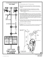
Top
Latch
C
L Device Mounting Holes,
Rods, & Strikes
Rod Guide
(2) 1/4-20 x 3/4" (19mm)
PFHMS
(3) 10-24 x 1/4" (6mm)
PPHMS
791 Strike
Bottom
Mounting
Plate
Bottom Bolt
Case
(2) 1/4-20 x 3/4" (19mm)
PFHMS
(3) 10-24 x 1-1/4" (32mm)
PPHMS
Bottom Bolt
Case
F
Device
CL
C
B
D
F
16-3/8
(416)
15
(381)
1/2
(13)
Figure 3.
Note:
726 Strike and top
bracket not shown.
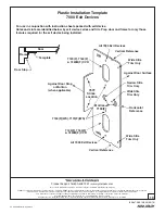
An ASSA ABLOY Group brand
80-9470-0010-000 (03-13)


