


4
7. Complete Installation
5. Rod Preparation & Assembly
A. Top Rod Sizing
1. For openings under 7' (2134mm), subtract the actual
opening height from 7' (2134mm).
Example: 6'8" (2032mm) opening
7'0" (2134mm) - 6'8" (2032mm)
= 4" (102mm)
Top Rod must have 4" (102mm) cut from end with
1/8” (3mm) thru hole. Use attached drill fixture to
locate and re-drill 1/8" (3mm) dia. hole thru the
top rod. Make sure rod bottoms out inside drill fixture
prior to drilling. (See Figure 5A).
2. For opening over 7' (2134mm), subtract 7' (2134mm)
from the actual opening height.
Example: 7'6" (2286mm) - 7'0" (2134mm)
= 6" (152mm).
Top Rod must have a 6" (152mm) extension added
to length (See below for available rod lengths).
B. Assemble Top Rod
Insert Top Rod Connector into sized Top Rod and Install
1/8" (3mm) x 1/2" (13mm) Roll Pin thru both pieces until
flush on both sides. (See Figure 5B).
Top Rod
Flat Face
(2 Sides)
Top Rod
Connector
Flush
1/8" (3mm)
x 1/2" (13mm)
36-1/8
(918)
1/8
(3)
Drill Fixture
3/8
(10)
Figure 5B: Top Rod Assembly
Figure 5A: Drill Pin Hole
Note:
Below listed instructions are based on a device
mounted 39-15/16" (1014mm) from finished floor
or threshold. Any deviation on device mounting
height must be accommodated to insure proper
device function.
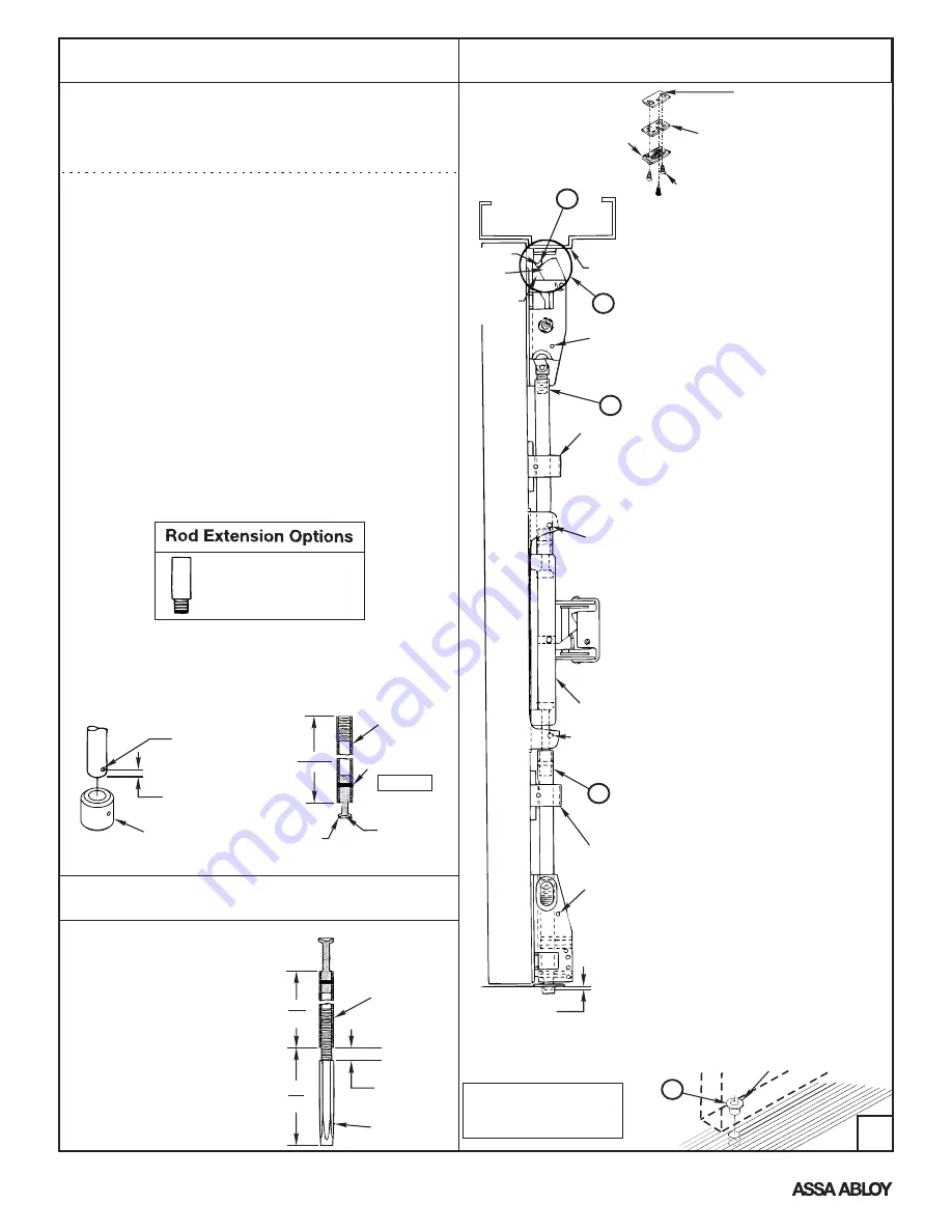
6. Bottom Bolt Assembly
A.
Thread Bottom Bolt into Bottom
Rod Assembly.
B.
Leave 1/2" (13mm)
for adjustment.
Bottom Rod
Assembly
Bolt
1/2
(13)
3-7/8
(98)
32-1/4
(812)
Adjustable
(Ref.)
Bolt
Engagement
Frame
Stop
Rod Guide
A2
A
3/8"
(10)
Cover
Screw
Hole
Cover
Screw
Hole
Cover
Screw
Hole
Cover
Screw
Hole
Note:
Bottom Bolt will retract to
1/8" (3mm) above Floor Strike.
Floor covering in the door path
must be laid out accordingly.
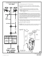
Top Strike Detail
Shim
(2) Supplied (Start With One)
Strike Plate
(Ridges Face Down)
791 Strike
(3) 10-24 x 3/4" (19mm) PFHMS
B2
790 STRIKE
(Press in place)
A. Install Top Rod and 791 Strike
1.
Thread Top Rod Assembly onto Top Latch.
Lift rod to fully retract Top Latchbolt.
Depress Pushpad and hold depressed.
Adjust top rod length until Rod Connector
seats into the Slide Assembly in latch case.
Note:
For 7170 devices, skip section (2a)
and 2(b). See the installation instructions
for the 726 strike on page 9.
2a. Position the Top Strike Roller between
the Tripping Lever and the Bolt on the
Top Latch. Verify hole positions and
prepare holes per Installation Instruction
Template.
b. Install Top Strike and Strike Plate using
(2) #10-24 x 3/4" (19mm) PFHMS thru
outer slots. Adjust and shim strike as
needed for zero door rattle. Add third
screw (#10-24 x 3/4" (19mm) PFHMS)
after final adjustments.
3. If Top Bolt does not remain retracted when
door is opened, Top Rod is too short. Pull
rod out of the guide and the slide then
rotate rod to increase length. Upper Bolt
should retract flat.
4. If upper latch will not deadlock, Top rod
is too long. Pull rod out of the guide and
the slide and rotate to decrease length.
* If 7170 LBR, skip section B.
B. Install Lower Rod and 790 Strike
1. With door open, actuate Pushpad to
retract upper latch. Hang Lower rod
from bottom of Slide and adjust bolt so
that it clears the finished floor by 1/4".
2. Verify location of pipe strike template.
Prepare the strike hole and install the
pipe strike. Set in place with appropriate
bonding material.
3. With the door open, actuate pushpad
to retract upper latch. Adjust bolt
height by pulling the rod out of the
guide and slide and rotating until the
bolt clears the pipe strike by 1/8".
C. Test device action by Touchbar,
by Trim, by Dogging
D. Install covers
A1
B
Rod Guide
Slide
Roller
Bolt
Tripping
Lever
60-1510-0280: 2" (51mm)
60-1510-0277: 6" (152mm)
60-1510-0278: 12" (305mm)
(Specify Device Finish)
An ASSA ABLOY Group brand
80-9470-0010-000 (03-13)


