of king pin are supported by needle roller bearings
pressed on the axle body. Oil seals are mounted on
the two ends of needle roller bearings, and oil cup is
fitted on the king pin.
Steering Wheel Bearing Pre-load
Information
1.
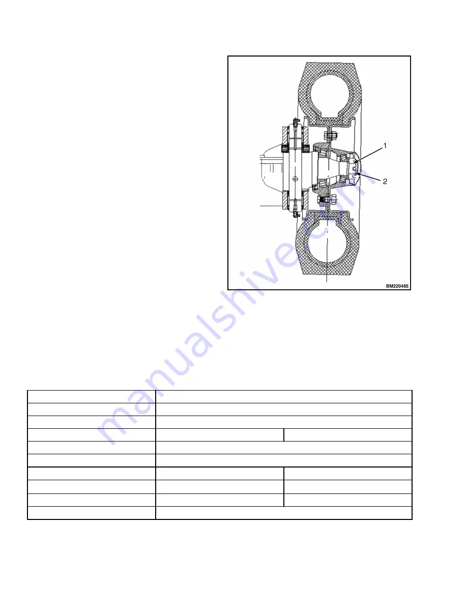
Grease the hub, internal and external bearings
and the inner cavity of the hub cap and lip of oil
seal. See Figure 23.
2.
Install the bearing outer ring onto the wheel hub,
and mount the wheel hub onto the shaft of
steering knuckle.
3.
Mount the flat washer and tighten the slot nut.
Torque to 206-235 N•m (151.9-173.3 lbf ft).
4.
Loosen the slot nut and then tighten the nut.
Torque to 9.8 N•m (7.2 lbf ft).
5.
Tap the wheel hub gently using a hammer.
Manually turn the wheel hub 3-4 times to ensure
a steady rotation. Torque to
2.9-7.8 N•m (2.1-5.8 lbf ft).
6.
When rotating torque is higher than the specified
value, loosen nut by 1/6 turn, then check torque
again.
7.
Lock the slot nut using cotter pin, when specified
rotating torque is reached.
1. SLOT NUT
2. GREASING LOCATION
Figure 23. Adjustment for Pre-loading
Brake System
Type
Front Twin Wheel Brake, Internal Expansion, Hydraulic
Pedal Lever Ratio
5.66
Master Cylinder Diameter
19.05 mm (0.75 in.)
Wheel Brake
2-2.5T
3-3.5T
Type
Dual Servo Type with Parking Brake
Wheel Cylinder Diameter
28.6 mm (1.1 in.)
Size of Brake Shoe (L×W×T)
324×60×7 mm (12.8×2.4×0.28 in.) 348×76×8 mm (13.7×2.99×0.31 in.)
Area of Brake Shoe
194.4 cm
2
×4
264 cm
2
×4
Inner Diameter of Brake Drum
310 mm (12.2 in.)
314 mm (12.4 in.)
Parking Brake
Front Twin Wheel Brake, Internal Expansion, and Hydraulic Type
Brake System
8000 YRM 2199
26
Summary of Contents for A7S1
Page 4: ......
Page 7: ...TABLE OF CONTENTS Continued Lubrication System 83 PDM Schematics 85 Table of Contents iii ...
Page 8: ......
Page 36: ...Figure 25 2 2 5T Wheel Brakes Brake System 8000 YRM 2199 28 ...
Page 54: ...Figure 43 Oil Circuit of Hydraulic System Hydraulic System 8000 YRM 2199 46 ...
Page 69: ...Figure 58 Two Stage Free Lift and Three Stage Masts 8000 YRM 2199 Lifting System 61 ...
Page 76: ...Figure 61 With NISSAN engine K21 K25 Sheet 1 of 2 Electrical System 8000 YRM 2199 68 ...
Page 77: ...Figure 62 With NISSAN engine K21 K25 Sheet 2 of 2 8000 YRM 2199 Electrical System 69 ...
Page 78: ...Figure 63 With PSI engine Sheet 1 of 2 Electrical System 8000 YRM 2199 70 ...
Page 79: ...Figure 64 With PSI engine Sheet 2 of 2 8000 YRM 2199 Electrical System 71 ...
Page 80: ...Figure 65 With Mitsubishi engine S4S Sheet 1 of 2 Electrical System 8000 YRM 2199 72 ...
Page 81: ...Figure 66 With Mitsubishi engine S4S Sheet 2 of 2 8000 YRM 2199 Electrical System 73 ...
Page 82: ...Figure 67 With Xinchai engine Sheet 1 of 2 Electrical System 8000 YRM 2199 74 ...
Page 83: ...Figure 68 With Xinchai engine Sheet 2 of 2 8000 YRM 2199 Electrical System 75 ...
Page 84: ...Figure 69 With Yanmar engine 92 98 Sheet 1 of 2 Electrical System 8000 YRM 2199 76 ...
Page 85: ...Figure 70 With Yanmar engine 92 98 Sheet 2 of 2 8000 YRM 2199 Electrical System 77 ...
Page 86: ...Figure 71 With Yanmar engine 94 Sheet 1 of 2 Electrical System 8000 YRM 2199 78 ...
Page 87: ...Figure 72 With Yanmar engine 94 Sheet 2 of 2 8000 YRM 2199 Electrical System 79 ...
Page 88: ...Figure 73 Optional Accessories Electrical System 8000 YRM 2199 80 ...
Page 93: ...PDM Schematics 8000 YRM 2199 PDM Schematics 85 ...
Page 94: ......
Page 95: ...8000 YRM 2199 Figure 76 PDM Suitable For All Engines 87 88 blank ...
Page 96: ......
Page 97: ...8000 YRM 2199 Figure 77 PDM With OPS Suitable For All Engines 89 90 blank ...
Page 98: ......
Page 99: ......


