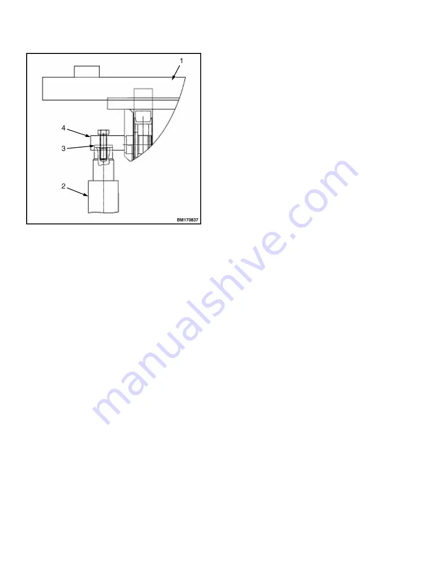
1. INNER MAST
2. LIFT CYLINDER
3. ADJUSTING WASHER
4. UPPER BEAM OF THE INNER MAST
b.
Raise the mast slowly until the maximum
stroke of the cylinder is reached, check
whether the two cylinders are synchronized.
c.
Add adjusting shims between piston rod head
and the upper beam of the inner mast. Make
sure the washer is 02.-0.5 mm (0.008-0.02 in.)
thick.
NOTE:
Safety precautions must be taken when
adjusting the cylinder.
d.
Adjust the tension of the chains.
Electrical System
OVERVIEW
The electrical system in this model series is a single-
line electrical system that utilizes anode bonding in the
truck’s electrical circuitry to ensure that the forklift truck
works properly in various conditions. The electrical
equipment is composed of following systems:
Power supply system
The power supply system consists of battery,
alternator, charging indicator light and other
components. It supplies power to the electric
equipment of the truck. The battery provides power
prior to starting the forklift. The alternator provides
power when the forklift runs, and at the same time
charges the battery. The charging indicator light is
used to display the charging status.
Starting system
The starting system is composed of glow plug (diesel
truck only), key switch, neutral switch, and starter
lamp. The function of the starting system is to start the
engine. After the key switch is turned on, the glow plug
heats up. The starting system has neutral protection
function; the truck will only start if the shift lever is at
the neutral position.
Ignition system (ICE forklift truck)
Gasoline equipped forklifts do not have a preheating
components as diesel forklift do. They have spark
plugs, and on some ICE engines a distributor and
spark plug wires are present for the ignition system to
function.
Preheating system (diesel forklift truck)
The preheating system mainly consists of preheating
plug (glow plug), preheating relay and time relay. The
preheating time is set to 10-13seconds, but can be
adjusted through time relay. Diesel with ECU electric
control system is available. A temperature sensor is
equipped to detect whether the current temperature
needs to be preheated to increase the service life of
components.
Electrical System
8000 YRM 2199
64
Summary of Contents for A7S1
Page 4: ......
Page 7: ...TABLE OF CONTENTS Continued Lubrication System 83 PDM Schematics 85 Table of Contents iii ...
Page 8: ......
Page 36: ...Figure 25 2 2 5T Wheel Brakes Brake System 8000 YRM 2199 28 ...
Page 54: ...Figure 43 Oil Circuit of Hydraulic System Hydraulic System 8000 YRM 2199 46 ...
Page 69: ...Figure 58 Two Stage Free Lift and Three Stage Masts 8000 YRM 2199 Lifting System 61 ...
Page 76: ...Figure 61 With NISSAN engine K21 K25 Sheet 1 of 2 Electrical System 8000 YRM 2199 68 ...
Page 77: ...Figure 62 With NISSAN engine K21 K25 Sheet 2 of 2 8000 YRM 2199 Electrical System 69 ...
Page 78: ...Figure 63 With PSI engine Sheet 1 of 2 Electrical System 8000 YRM 2199 70 ...
Page 79: ...Figure 64 With PSI engine Sheet 2 of 2 8000 YRM 2199 Electrical System 71 ...
Page 80: ...Figure 65 With Mitsubishi engine S4S Sheet 1 of 2 Electrical System 8000 YRM 2199 72 ...
Page 81: ...Figure 66 With Mitsubishi engine S4S Sheet 2 of 2 8000 YRM 2199 Electrical System 73 ...
Page 82: ...Figure 67 With Xinchai engine Sheet 1 of 2 Electrical System 8000 YRM 2199 74 ...
Page 83: ...Figure 68 With Xinchai engine Sheet 2 of 2 8000 YRM 2199 Electrical System 75 ...
Page 84: ...Figure 69 With Yanmar engine 92 98 Sheet 1 of 2 Electrical System 8000 YRM 2199 76 ...
Page 85: ...Figure 70 With Yanmar engine 92 98 Sheet 2 of 2 8000 YRM 2199 Electrical System 77 ...
Page 86: ...Figure 71 With Yanmar engine 94 Sheet 1 of 2 Electrical System 8000 YRM 2199 78 ...
Page 87: ...Figure 72 With Yanmar engine 94 Sheet 2 of 2 8000 YRM 2199 Electrical System 79 ...
Page 88: ...Figure 73 Optional Accessories Electrical System 8000 YRM 2199 80 ...
Page 93: ...PDM Schematics 8000 YRM 2199 PDM Schematics 85 ...
Page 94: ......
Page 95: ...8000 YRM 2199 Figure 76 PDM Suitable For All Engines 87 88 blank ...
Page 96: ......
Page 97: ...8000 YRM 2199 Figure 77 PDM With OPS Suitable For All Engines 89 90 blank ...
Page 98: ......
Page 99: ......


