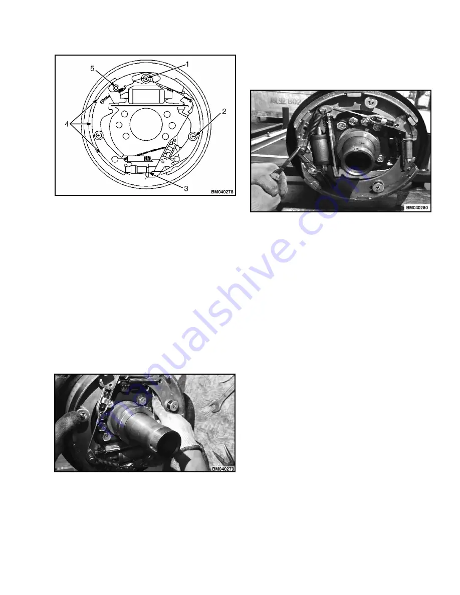
1. SUPPORT FACE OF BOTTOM PLATE
2. SUPPORT PIN OF LEVER L H BRAKE
3. SUPPORT PIN
4. ADJUSTER THREAD AND OTHER ROTATING
PARTS
5. CONTACT FACE OF BRAKE SHOE AND
WASHER CUP
Figure 35. For 2-3.5T Forklift Truck
6.
Mount the brake cable assembly onto the bottom
plate using E-shaped retainer ring.
7.
Mount the brake shoes onto the bottom plate
using the fixing spring. Install the washer, cup and
the adjusting lever. Mount the bottom part of the
secondary brakes shoe with fixing spring. Make
sure that the pressure seat is fitted in the holes of
brake shoes and adjusting lever.
8.
Mount the compressed spring onto the hand
brake push rod. Install the push rod onto the
brake shoes.
9.
Mount the guide plate of brake shoes onto the
support pin. Install the return spring of brake
shoes.
10.
Install adjuster, adjuster spring, top rod, and
return spring for top rod.
Check the following:
•
Adjuster thread direction and installation
direction.
-
For 2-2.5T trucks, right-hand thread is used
for left brake, while the left-hand thread is
used for right brake.
-
For 3-3.5T trucks, left-hand thread is used
for left brake, while right-hand thread is
used for right brake.
•
Adjuster spring direction The tooth part of
adjuster must not contact the spring.
•
Top rod return spring direction. The spring hook
must be installed on the opposite side of the top
rod at the end of the support pin.
•
Top rod and top rod return spring shall be fixed
inside the slot of support pin.
•
Make sure that the lower end of adjusting lever
contacts the tooth of the adjuster.
8000 YRM 2199
Brake System
37
Summary of Contents for A7S1
Page 4: ......
Page 7: ...TABLE OF CONTENTS Continued Lubrication System 83 PDM Schematics 85 Table of Contents iii ...
Page 8: ......
Page 36: ...Figure 25 2 2 5T Wheel Brakes Brake System 8000 YRM 2199 28 ...
Page 54: ...Figure 43 Oil Circuit of Hydraulic System Hydraulic System 8000 YRM 2199 46 ...
Page 69: ...Figure 58 Two Stage Free Lift and Three Stage Masts 8000 YRM 2199 Lifting System 61 ...
Page 76: ...Figure 61 With NISSAN engine K21 K25 Sheet 1 of 2 Electrical System 8000 YRM 2199 68 ...
Page 77: ...Figure 62 With NISSAN engine K21 K25 Sheet 2 of 2 8000 YRM 2199 Electrical System 69 ...
Page 78: ...Figure 63 With PSI engine Sheet 1 of 2 Electrical System 8000 YRM 2199 70 ...
Page 79: ...Figure 64 With PSI engine Sheet 2 of 2 8000 YRM 2199 Electrical System 71 ...
Page 80: ...Figure 65 With Mitsubishi engine S4S Sheet 1 of 2 Electrical System 8000 YRM 2199 72 ...
Page 81: ...Figure 66 With Mitsubishi engine S4S Sheet 2 of 2 8000 YRM 2199 Electrical System 73 ...
Page 82: ...Figure 67 With Xinchai engine Sheet 1 of 2 Electrical System 8000 YRM 2199 74 ...
Page 83: ...Figure 68 With Xinchai engine Sheet 2 of 2 8000 YRM 2199 Electrical System 75 ...
Page 84: ...Figure 69 With Yanmar engine 92 98 Sheet 1 of 2 Electrical System 8000 YRM 2199 76 ...
Page 85: ...Figure 70 With Yanmar engine 92 98 Sheet 2 of 2 8000 YRM 2199 Electrical System 77 ...
Page 86: ...Figure 71 With Yanmar engine 94 Sheet 1 of 2 Electrical System 8000 YRM 2199 78 ...
Page 87: ...Figure 72 With Yanmar engine 94 Sheet 2 of 2 8000 YRM 2199 Electrical System 79 ...
Page 88: ...Figure 73 Optional Accessories Electrical System 8000 YRM 2199 80 ...
Page 93: ...PDM Schematics 8000 YRM 2199 PDM Schematics 85 ...
Page 94: ......
Page 95: ...8000 YRM 2199 Figure 76 PDM Suitable For All Engines 87 88 blank ...
Page 96: ......
Page 97: ...8000 YRM 2199 Figure 77 PDM With OPS Suitable For All Engines 89 90 blank ...
Page 98: ......
Page 99: ......


