Part of ASSA ABLOY
P/N YRD400-KD-0022 Rev A
Trusted every day
6
Check Your Door Guide
1/4
1/8
3/8
5/8
3/4
7/8
0
1
2
3
1/4
1/8
3/8
5/8
3/4
7/8
1/4
1/8
3/8
5/8
3/4
7/8
1/2
1/2
1/2
I
B
Blue
C
Black
D
Silver
E
F
4
5
1/2
1/2
1/4
3/4
1/4
1/4
1/2
1/8
3/8
5/8
7/8
1/8
3/8
5/8
1/8
3/8
A
A. 2" Minimum clearance between top of
existing lever/knob rose (trim) and center
of deadbolt hole.
2" tolerance for optimal Door Sense
location.
B. 1-3/8" Door Thickness se blue Screw
; u
Set B (shortest set).
C. 1-3/8" - 1-3/4" Door Thickness; use black
Screw Set C.
D. 2" - 2-1/4" Door Thickness; use
silver Screw Set D (longest set).
E
; u
. 2-3/8" Backset se Out of Box latch
setting.
F. 2-3/4" Backset; adjust latch setting.
Instructions on how to adjust the latch
are included in manual.
G. 1-1/2" Face Bore Diameter. Instructions
on how to remove the black adapter from
the lock are included in manual.
1-1/2" tolerance from inside door frame
edge for optimal DoorSense location.
H. 2-1/8" Face Bore Diameter.
I. Edge Bore Diameter and Depth.
Cross Bore Diameter.
H
3/4
7/8
6
7
1/2
1/4
3/4
1/8
3/8
5/8
7/8
3/4
7/8
5/8
CAUTION:
If printed from electronic file,
Measure ruler to check scale.
set print scale to 1:1.
G
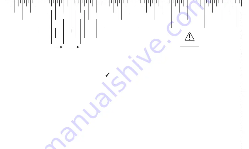
To ensure a successful installation, measure each aspect of your door and frame, as shown in panels (left side of sheet) using
the ruler above. Make sure all of your dimensions are a . See letter definitions below for guidance.
Cut Her
e


