Copyright ©2018, 2020 ASSA ABLOY Access and Egress Hardware Group, Inc. All rights reserved. Reproduction in whole or in
part without the express written permission of ASSA ABLOY Access and Egress Hardware Group, Inc. is prohibited.
For technical support contact Yale
®
at 800.438.1951 x5033 or support@yalelocks.com
10
Delayed Egress
Installation Instructions
7100, 7200 Series Exit Device
80-9470-0162-000 10/20
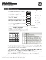
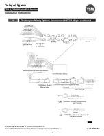
Figure 5
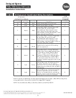
Pin Number
Input/Output
Wire Color
Description
Pin Number
NC
Input/Output
Violet
C, LBM or C, Trim Mon. or ET(-)
1
NC
Input/Output
Gray
NO, LBM or NO, Trim Mon. or ET(+)
2
NC
Input/Output
Pink
NC, LBM or NC, Trim Mon.
3
2
Input
Tan
Door Position Switch Input-Input sense for DPS
switch option
4
J2 Connector (See Figure 5 below.)
7
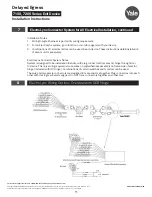
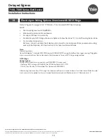
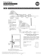
ElectroLynx Connector System for All Electrical Installation
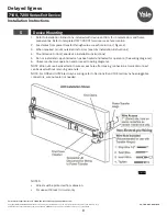
1. Mount exit device per instruction sheet provided.
2. Plug exit device connector into raceway connector in door. Feed through 1" (25mm) hole in door.
Install rail mounting end clamp bracket with two (2) screws supplied. Install end cap.
3. Plug raceway connector from edge of door into electric hinge connector and feed wires back
through door prep. Mount electric hinge to door.
A. If wiring now, wire frame side wires, to wires on pigtail harness, on hinge as required by
using connectors allowed by local code. Plug pigtail harness connector into electric hinge
connector. Feed harness through frame prep and mount electric hinge.
B. If wiring later, plug pigtail harness connector into electric hinge connector. Feed harness
through frame prep and mount electric hinge.
NOTE: ElectroLynx QC12 Hinge is required if DPS and/or any options shown are required.
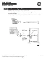
NOTE: Refer to Section 25 if replacing legacy PCBA/wiring with new PCBA/wiring.
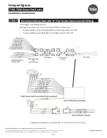
Top View
Bottom
View
4-Pin ElectroLynx Connector
6
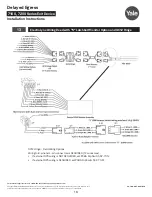
Wiring Layout: Input/Output Wiring Descriptions, continued


