background image

2

Key Fob

Can be used outside the premises and 
kept on your keyring. 
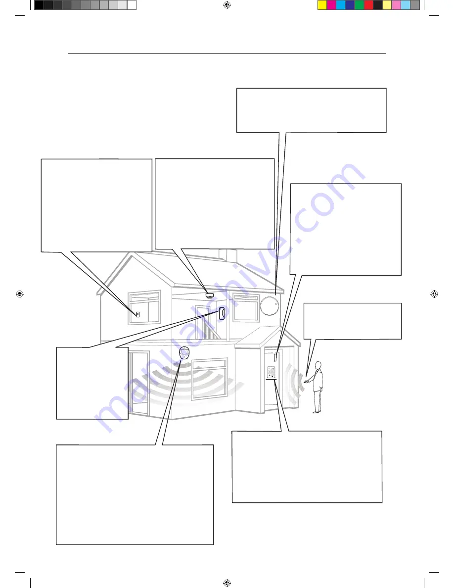
Location planning

Operating range


All devices must be within 30 metres of the Siren unit and must 
not be mounted on or near large metal objects. Avoid obvious 
sources of electrical interference such as fridges and microwave 
ovens. 
 

Tamper switches 

When mounting devices ensure that any tamper switches close 
fully. On uneven surfaces it may be necessary to place packing 
behind the switch for reliable operation. 

1

Work out the best places to locate the devices for maximum protection. Having chosen the 
locations do not mount at this stage.

Smoke Detector 

• Mount in the middle of the ceiling at the top of
   a stairwell, or on the centre of hallway ceilings
   where smoke would most likely be detected.
• Do not mount in corners or above cooking
   appliances and heaters.
• Install additional detectors if there are closed
   doors preventing smoke from reaching
   detectors.

External Siren (EF-KIT1 ONLY)


Choose a position on an external wall where the
Siren would be most prominent. Mount as high
as possible, out of easy reach.

Panic Button

The Panic Button provides extra protection 
for you and your family. When help is 
needed the button can activate your alarm 
immediately - even when the system is 
disarmed. 

•  Mount on flat wall surface
•  Designed for indoor use only
•  Out of reach of children
•  Hidden from view while easily accessible.

Extend the system


Extend the system in the future to increase your security or as your 
needs change. 
For example, add extra PIR Motion Detectors in bedrooms and extra 
Door/Window Contacts (30 devices in total, including Key Pad). 

Yale

R

ale

Y

Door/Window Contact

Use one Door/Window Contact on a door 
that is used as the main point of entry and 
exit, usually your front door. The other 
Door/Window Contact can be used to 
protect another entry point such as a rear 

door. 
• Mount as high as possible. 
• Do not aim a PIR Motion Detector at this
   door or window.
 

ale

Y

1

2

3

6

5

4
7

8

9

0

ale

Y

Indoor Siren  
(EF-KIT4 ONLY)

Choose a position on 
an internal wall where 
the Siren would be most 
prominent. Mount as 
high as possible, out of 
easy reach

PIR Motion Detector

• Mount in a position such that an intruder would normally 
   move across a PIRs field of view. 
• Height should be between 1.9 and 2 metres above floor level. 
• Location in a corner will ensure wider room coverage. 
• Do not mount a PIR where its field of view will be obstructed
   e.g. by curtains, ornaments etc. 
• Do not point directly at sources of heat e.g. fires or boilers, 
   and do not position directly above radiators. 
• Avoid mounting a PIR directly facing a window. 
• Do not point a PIR at a door protected by a Door/Window
   Contact.

Key Pad Remote Control 

• The Key Pad should be sited next to the main point of 
   entry/exit so that the system can be disarmed/armed 
   within 20 seconds of entering/leaving the premises. 
• Ensure that the Key Pad is not visible from the outside 
   of the premises. 
• Mount at chest height for ease of use. 
• Designed for indoor use only.

Summary of Contents for EF-KIT1

Page 1: ...he correct tools are used Wear goggles or protective clothing where required The Siren is extremely loud please ensure you replace the cover and retreat to a safe distance before testing Special Notes on Compatibility This alarm system is NOT compatible with HSA6000 series and HSA3000 series accessories Please note the prefix EF on the front of the part number to indicate compatibility Note Not co...

Page 2: ...xtend the system Extend the system in the future to increase your security or as your needs change For example add extra PIR Motion Detectors in bedrooms and extra Door Window Contacts 30 devices in total including Key Pad Yale R ale Y Door Window Contact Use one Door Window Contact on a door that is used as the main point of entry and exit usually your front door The other Door Window Contact can...

Page 3: ...e Y 1 2 3 6 5 4 7 8 9 0 Panic button A Panic button B Disarm HomeArm LED Learn button Press 8 and 9 together Pull out the plastic battery saver tab at the back of the Key Pad This will activate the batteries Button not in use Tamper Switch Learn Button Power Switch Programming Dip Switch Indoor Siren EF KIT4 ONLY Siren Setup 1 Remove the cover by unscrewing the single screw located on the lid 2 En...

Page 4: ...s as shown Keyfob remote control accessory Slide off the battery cover insert the 23A MN21 battery as shown and replace battery cover Switch to on Help button accessory Remove the cover by loosening the fixing screw and insert the 12V battery supplied as shown Please ensure you observe battery polarity Tamper switch per ch xtension terminals Learn Test button Learn Test button On Off switch Key Fo...

Page 5: ...sories please press the learn button on the accessories when the power switch is first turned on and in learn mode to learn each one into the system Do not press the Siren learn button See Chapter 2 for learn button location The Siren will beep each time it receives a learn signal to indicate that the accessory is now recognised by the system i This system is equipped with the latest type of radio...

Page 6: ... base where the plastic is thinner The center two knockout holes are for flat wall mounting while the 4 side holes are for corner mounting Wall fixing knockouts x2 Corner fixing knockouts x4 Battery tab 2 Drill holes into the wall using the knockout holes on the base as a template 3 Fit wall plugs and secure the PIR base with the screws provided 4 Fit the PIR back together and tighten the bottom s...

Page 7: ...hinner 2 Using the holes as a template drill holes in the surface and insert wall plugs if fixing into plaster or brick Screw the rear case to the wall Replace the cover and tighten the screw Mounting the Smoke Detector 1 The base has two mounting slots Using the slots as a template drill holes and insert the wall plugs if fixing to plaster Screw the rear case to the ceiling using the screws provi...

Page 8: ...ored except for the tamper switches The system can be armed when inside the protected area of your premises Key Fob will arm the system instantly without a 20 second exit delay Any detector activated afterwards will trigger an instant alarm The system should be armed when outside the protected area of your premises i Key Pad If the system has been armed with a Key Pad there will be a 20 second ent...

Page 9: ...rm is armed prior to activation the system will re arm after being silenced with the Panic Button 3 The system will require a reset at the Smart Hub after being silenced with the Panic Button Using your Smoke Detector Smoke Detection When smoke is detected the device will activate for a minimum of 10 seconds with a two tone alarm and flashing LED The Detector will send a radio signal to the Smart ...

Page 10: ...Arm and Emergency buttons together continuously for 5 seconds until the LED stops flashing to rearm tamper protection Adding devices to an already installed system The installed system will be controlled by either a Key Fob s or a Key Pad s Using your existing Key Pad 1 Enter Setting mode Press Panic Button A followed by the PIN Code Indicated by a continuously flashing LED 2 Switch OFF system tam...

Page 11: ...spring is fully depressed when re fitting the PIR to the back case If this has not been done correctly this will be indicated by a flashing LED on the PIR Siren Battery Change When the batteries start getting low the Siren will produce a series of audible pips and flashes during arming and disarming 1 Switch off tamper protection as described on page 9 Table 1 2 Remove the Siren lid and switch the...

Page 12: ...w the Key Pad case back on and the battery change is complete Panic Button Battery Change When the battery is low the LED will glow dimly when the button is pressed The battery is changed as follows 1 Loosen the bottom case screw and take button cover off base 2 Insert the new CR2032 coin cell battery with the side uppermost see picture below 3 Replace button cover Press the button and check that ...

Page 13: ...ery compartment and ensure the battery pin stays above the battery The Siren will not respond to the disarm PIN code Ensure that the Key Pad mode is correct by entering test mode and pressing Panic Button A then 8 Forgotten user PIN code See Key Pad reset procedure on page 14 PIR Motion Detector PIR does not respond to motion Previous motion has triggered the PIR sleep timer and is preventing subs...

Page 14: ...learn button on device to learnt in Key Pad reset procedure The Key Pad is tamper protected Please ensure the siren tamper is disabled before you open the Key Pad cover See Page 9 table 1 for siren tamper disable procedure Open cover and remove battery Reinsert with the number 3 key pressed taking care 3 is held down The Key Pad will go back to the 0000 Key Pad code The Key Pad will now have to be...

Page 15: ... 6V 4 x D alkaline batteries PIR Motion Detector Alarm processing Microprocessor controlled dual edge sequential pulse count with pulse length discrimination Radio 868MHz FM Power supply 4 5V 3 x AAA alkaline batteries Movement detection range 12 metres 110 Door Window Contact Radio 868MHz FM Power supply 3V CR2032 lithium coin cell battery Smoke Detector Radio 868MHz FM Power supply 4 5V 3 x AA a...

Page 16: ...nd WV13 3PW Declare under our sole responsibility that the following product s Yale Model SR PIR EF PIR SR PETPIR EF PETPIR SR DC EF DC SR KF EF KF SR KP FE KP SR PB EF PB SR SD EF SD SR BX EF BX SR PC EF BXINT SR PVC EF PANEL SR PS EF IPBOX SR RS EF INTBOX SR SR EF Easy Fit Alarm Kits SR EIR SR SR SR WS SR CO SR HUB SR HUL SR HSL SR MZ8 SR Smart Home Alarm kits SR Standard Alarm kits SR Smartphon...

Reviews: