3
Unpack all the parts
The easiest way to get to know the system and get it up and running quickly is to get all the
devices and accessories programmed before locating and mounting them.
2
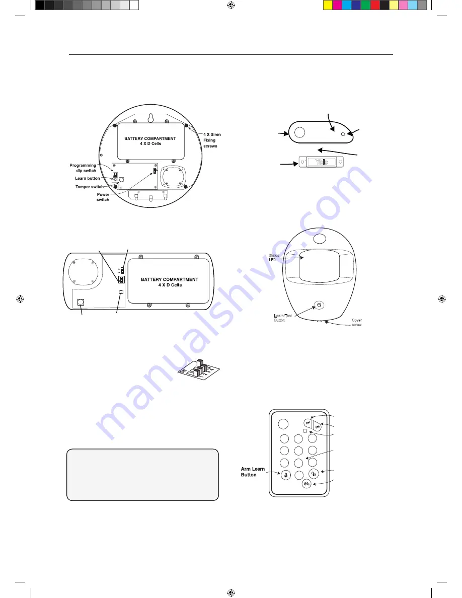
Pull out the plastic pull tab on the back of the PIR.
This will activate the batteries.
(A red light can be seen flashing through the lens. This will last for
30 seconds indicating the component’s initiation. )
ale
Y
Status
LED
Learn/Test
Button
Cover
screw
Pull out the plastic pull tab found on the side of
the main unit. This will activate the battery.
aleY
Learn/Test
button
LED
Gap no more
than 10mm
Magnet
Sensor
ale
Y
1
2
3
6
5
4
7
8
9
0
Panic button A
Panic button B
Disarm
HomeArm
LED
Learn button=
Press 8 and 9 together
/
Pull out the plastic battery saver tab at the back of
the Key Pad. This will activate the batteries.
(Button not in
use)
Tamper Switch
Learn Button
Power Switch
Programming
Dip Switch
Indoor Siren (EF-KIT4 ONLY)
Siren Setup
1.
Remove the cover by unscrewing
the single screw located on the lid.
2.
Ensure the dip switches position
are as shown in the diagram. If the
switches are in the wrong position, please change
accordingly.
DO NOT SWITCH THE POWER SWITCH TO ON
POSITION AT THIS STAGE.
NORMAL
Dip Switches
DSW 1: Siren Reset
DSW 2: Jamming detection
DSW 3: Not in use (Supervision)
DSW 4: Siren as Master/Slave (On position only)
i
External Siren (EF-KIT1 ONLY)
Door/Window Contacts
PIR Motion Detectors
Key Pad


