LOAD WEIGHT INDICATOR
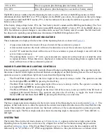
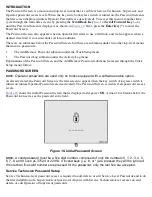
The Load Weight indicator for the lift truck, shown as 99999 beside the Load Weight Icon in
,
appears at the midpoint of the right side of the Operating Screen. If the lift truck supports the Load Weight
feature, the Operating Screen will display the load weight during any mast hydraulic command and for five
seconds afterwards.
The Load Weight Icon indicates whether lb (pound) or kg (kilogram) units are being used. Use the procedures
described in the Set Units Menu topic in the Display Menu section to set the load units for this lift truck. Use
the procedures in the Load Weight Display topic in the Calibration Menu section to calibrate the load weight
for this lift truck.
System Off/Alert Screens
INTRODUCTION
Several screens appear only briefly on the Operating Screen. These include the System Off Screen and Alert
Screens. The purpose of the System Off Screen is to supply brief status information as the system is powered
off. Alert Screens appear momentarily to attract attention. The topics that follow provide more information
about these types of screens.
SYSTEM OFF SCREEN
When the lift truck power is first turned
OFF
, the System Off Screen is displayed for five seconds. The
system will also display this screen for five seconds if the
Scroll Forward Key
(
—
▸
) is pressed while the
truck is powered
OFF
.
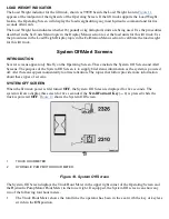
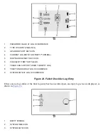
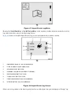
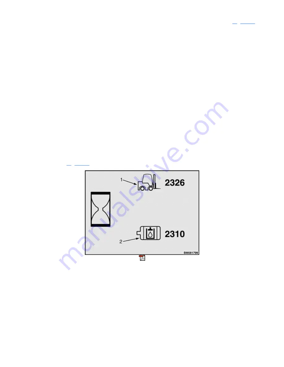
shows the System Off Screen.
1.
TRUCK HOUR METER
2.
HYDRAULIC PUMP MOTOR HOUR METER
Figure 13. System Off Screen
The System Off Screen displays the Truck Hour Meter in the upper right corner of the Operating Screen and
the Hydraulic Pump Motor Hour Meter in the lower right. If equipped, the System Off screen can show any
two of the following four hour meters.
•
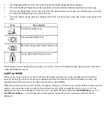
The Truck Hour Meter shows the total time the operator has been in the seat with the key or keyless
switch in the
ON
position.
Summary of Contents for ERC030VA
Page 8: ...Figure 3 Supervisor Flowchart Sheet 1 of 4 ...
Page 9: ...Figure 3 Supervisor Flowchart Sheet 2 of 4 ...
Page 10: ...Figure 3 Supervisor Flowchart Sheet 3 of 4 ...
Page 11: ...Figure 3 Supervisor Flowchart Sheet 4 of 4 Table 1 Supervisor Menu Flowchart A B C D E F G H ...
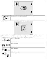
Page 21: ...Hydraulics Icon Alert Screens Cycle the Key Secure Battery Release Park Brake ...
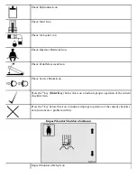
Page 22: ...Operator Out of Seat Release Pedal Release Hydraulic Input Traction Switch ...
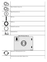
Page 23: ...Hydraulic Switch Temperature Too High Lift Limit Charge Battery ...
Page 26: ...Display Title Screen Status Title Screen Truck Setup Title Screen ...
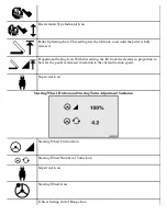
Page 105: ...Figure 71 Steering Wheel Number of Turns Valid Entry ...

